

American-Machinist Nov-8-1900
The-Gleason-Bevel-Gear-Tooth
Planer-Traceing a template-cutter
New Radial Drilling Machine.
American-Machinist-Nov-8-1900
The-Gleason-Bevel-Gear-Toot-Planer
-Machine Gear Tooth-tracer-cutter
The-Gleason-Bevel-Gear-Toot-Planer-Machine-tooth-tracer-cutter-Mechanism-Gleason-Templet-Bevel-Pinion-Tooth-Generating-Machine .

-------- AM
A JOURNAL FOR MACHINISTS, ENGINEERS, FOUNDERS, BOILER MAKERS, PATTERN MAKERS, AND BLACKSMITHS,
WEEKLY. NEW YORK, 1900.
FIG. 106.
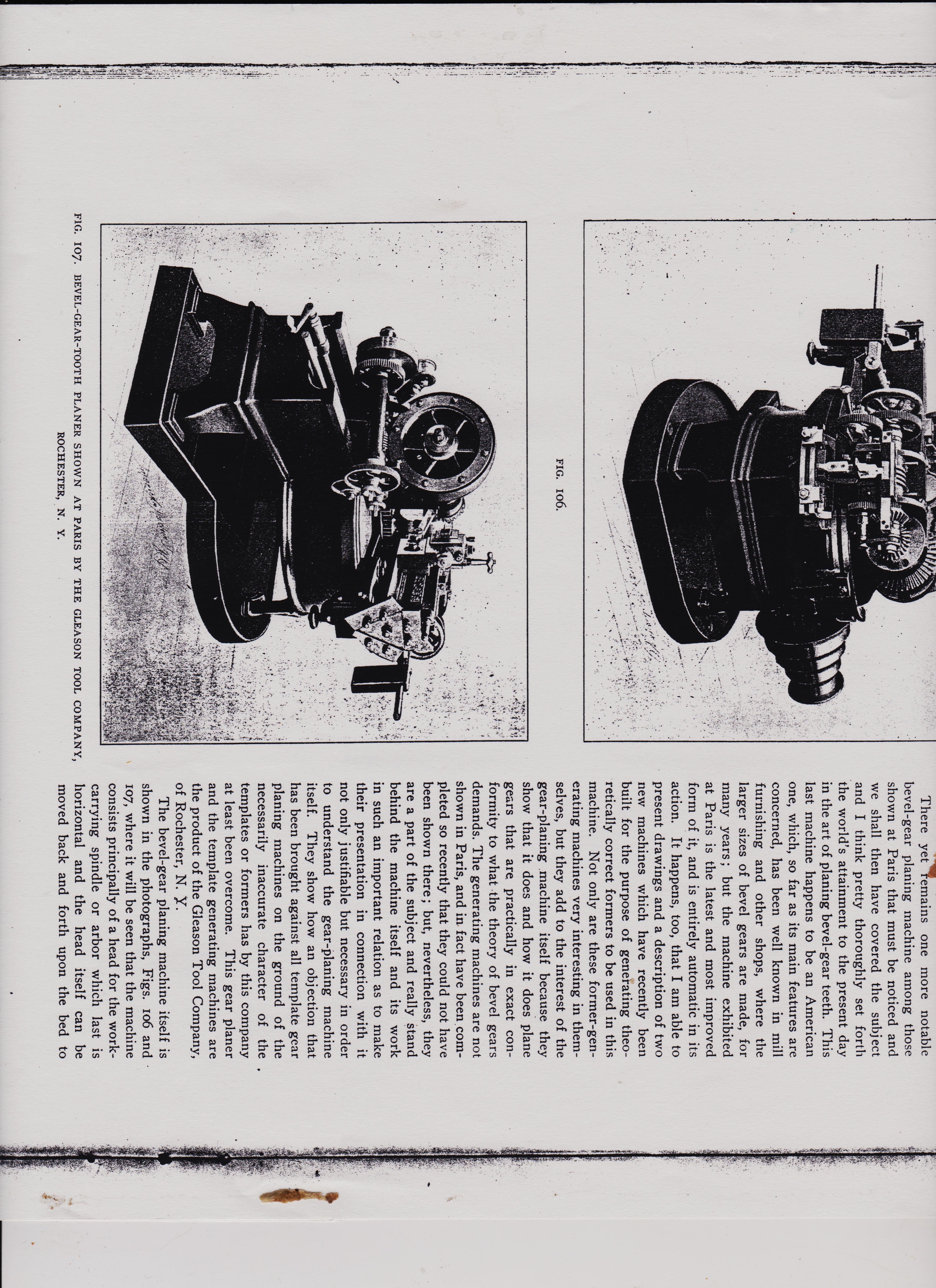
F1G. 107. BEVEL-GEAR-TOOTH PLANER SHOWN AT PARIS BY THE GLEASON TOOL ROCHESTER, N. Y. COMPANY,
There yet remains one more notable bevel-gear planing machine among those shown at Paris that must be noticed and we shall then have covered the subject and I think pretty thoroughly set forth the world's attainment to the present day in the art of planing bevel-gear teeth. This last machine happens to be an American one, which, so far as its main features are concerned, has been well known in mill furnishing and other shops, where the larger sizes of bevel gears are made, for many years ; but the machine exhibited at Paris is the latest and most improved form of it, and is entirely automatic in its action. It happens, too, that I am able to present drawings and a description of two new machines which have recently been built for the purpose of generating theo-retically correct formers to be used in this machine. Not only are these former-gen-erating machines very interesting in them-selves, but they add to the interest of the gear-planing machine itself because they show that it does and how it does plane gears that are practically in exact con-formity to what the theory of bevel gears demands. The generating machines are not shown in Paris, and in fact have been com-pleted so recently that they could not have been shown there but, nevertheless, they are a part of the subject and really stand behind the machine itself and its work in such an important relation as to make their presentation in connection with it not only justifiable but necessary in order to understand the gear-planing machine itself. They show how an objection that has been brought against all template gear planing machines on the ground of the necessarily inaccurate character of the templates or formers has by this company at least been overcome. This gear planer and the template generating machines are the product of the Gleason Tool Company, of Rochester, N. Y. The bevel-gear planing machine itself is shown in the photographs, Figs. 106 and 107, where it will be seen that the machine consists principally of a head for the work-carrying spindle or arbor which last is horizontal and the head itself can be moved back and forth upon the bed to mine is wanted 96 inches in diameter, it would need to be about 1,275 pounds, and, as I want this engine to run very nice, I will call it 1,500 pounds, which will make
November 8, 19oo.
to 7,300 pounds. All I have to do is to pick the right one to use. I have consulted Unwin, Rankine and Kent, and have my head full of velocity, momentum, inertia,
1058-28
in the pattern shop, and told the pattern maker he would have to use his own judgment as to some of the details, as I had not time to figure them all out (it is hard work to measure up all the sizes on a bed), and now I have lots of figures for my flywheel. It is to be 8 feet in diameter, and, according to the formulas in my hnnkc ran AMERICAN MACHINIST variation, centrifugal force and factor of safety, until I am sure I am not very sure of knowing anything very definite, except that a very heavy flywheel is harder to make run jerky than a light one, and costs more money to build. I tried my universal formula on the fly-wheel. The one I measured was 54 inches diameter and weighs 700 pounds. As
FIG. 106.
it run 2Q0 pounds nicer than the other one. I expect we will have some fun when we .come to make this engine, and I will let you know if we do. I did not try to get my rule for designing patented. I was afraid if I searched the records I might find it not entirely new ; but I can rec-ommend it as being good, if you will use a proper starting point and lots of experi-ence and horse sense with it. You have to do that with any of the others, and most of them are harder to work than this one. W. OSBORNE.
The Paris Exposition—XIV.
AN AMERICAN BEVEL-GEAR PLANING MACHINE.
There yet remains one more notable bevel-gear planing machine among those shown at Paris that must be noticed and we shall then have covered the subject and I think pretty thoroughly set forth the world's attainment to the present day in the art of planing bevel-gear teeth. This last machine happens to be an American one, which, so far as its main features are concerned, has been well known in mill furnishing and other shops, where the larger sizes of bevel gears are made, for many years ; but the machine exhibited at Paris is the latest and most improved form of it, and is entirely automatic in its action. It happens, too, that I am able to present drawings and a description of two new machines which have recently been built for the purpose of generating theo-retically correct formers to be used in this machine. Not only are these former-gen, erating machines very interesting in them-selves, but they add to the interest of the gear-planing machine itself because they show that it does and how it does plane gears that are practically in exact con-formity to what the theory of bevel gears demands. The generating machines are not shown in Paris, and in fact have been com-
AMERICAN-MACHINIST-1900.
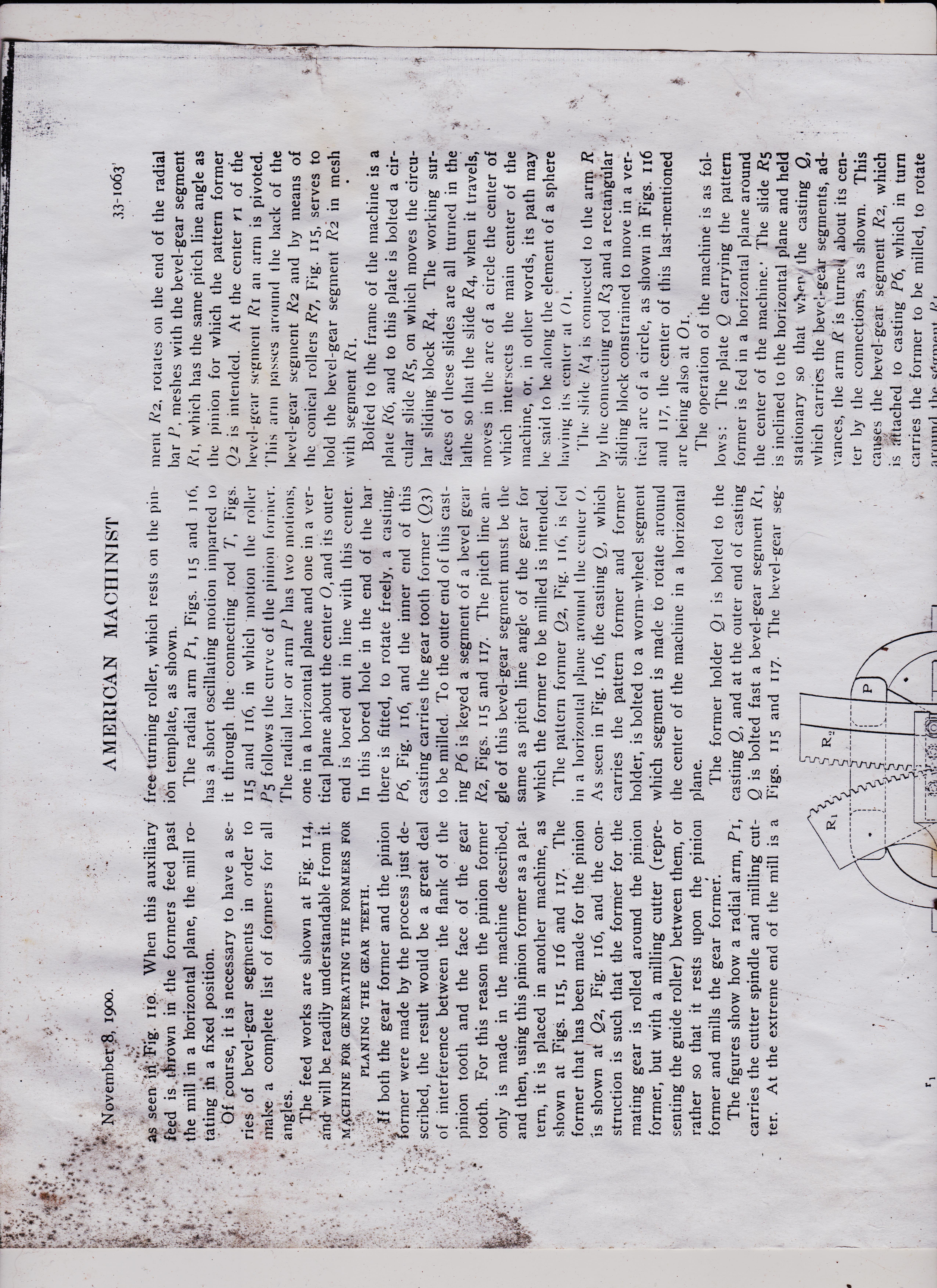
>has the swinging motion in a horizontal plane given to it by the feed motion al-ready referred to, but it also swings in a vertical plane about a center which inter-sects the other center lines and this ver-tical swinging motion is controlled by the
accommodate gears of various proportions having hubs of unusual length. also a clear space in front of the or those There is blank so that where a hub happens to ex-
AMERICAN MACHINIST
< A tool-carrying head reciprocates upon a slide mounted upon the saddle referred to and is moved by a crank and connection best seen in Fig. 107. This slide not only tend beyond the apex of the gear itself the machine is still able to handle such a gear. On the spindle that holds the work there is the usual master wheel by which the divisions are made and this is turned automatically at the proper times by a friction-
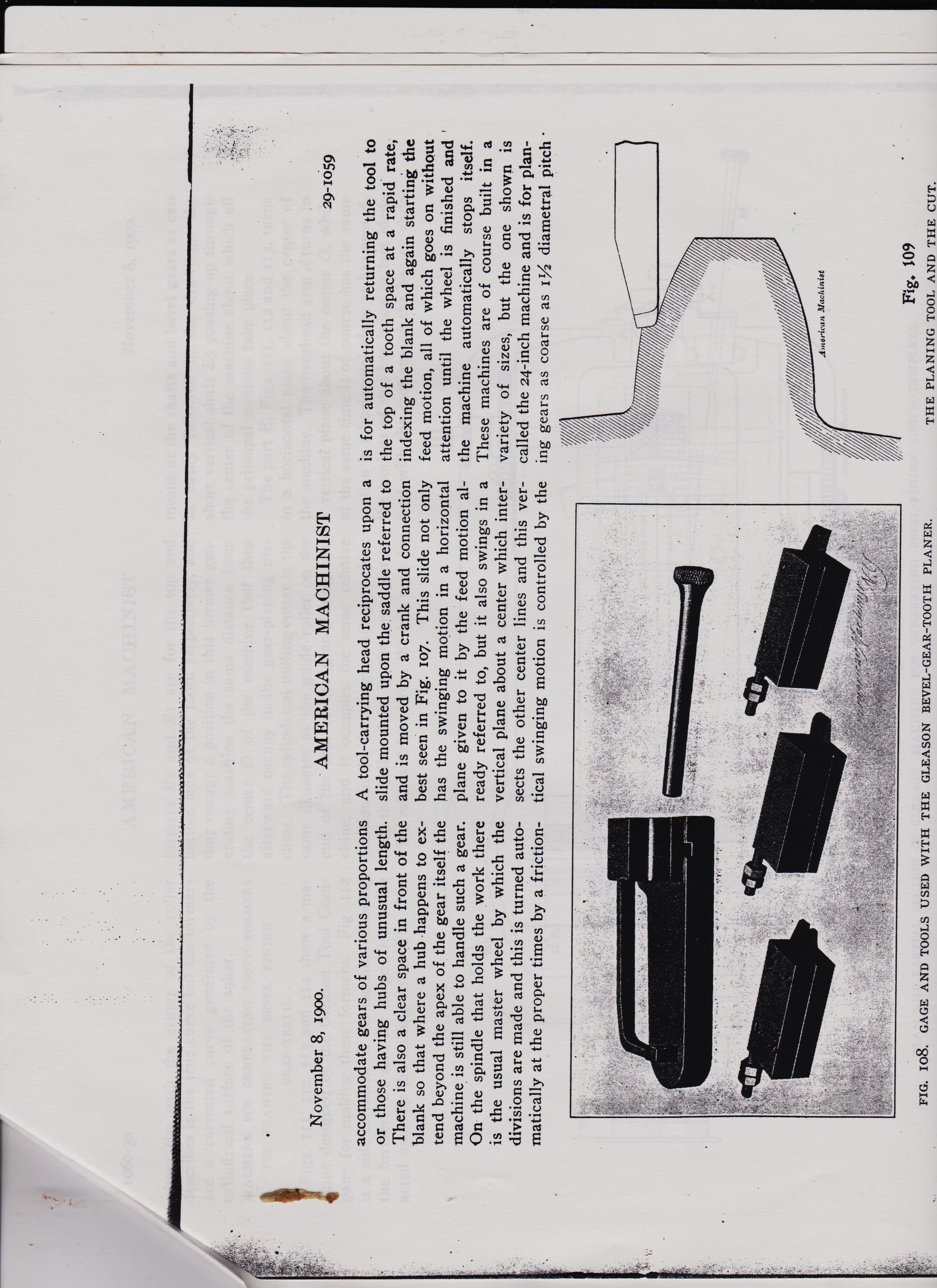
FIG. 108. GAGE AND TOOLS USED WITH THE GLEASON BEVEL-GEAR-TOOTH PLANER. 29-1059
is for automatically returning the tool to the top of a tooth space at a rapid rate, indexing the blank and again starting the feed motion, all of which goes on without attention until the wheel is finished and the machine automatically stops itself. These machines are of course built in a variety of sizes, but the one shown is called the 24-inch machine and is for planing gears as coarse as 'IA diametral pitch American Machinist
Fig. 109 THE PLANING TOOL AND THE CUT.
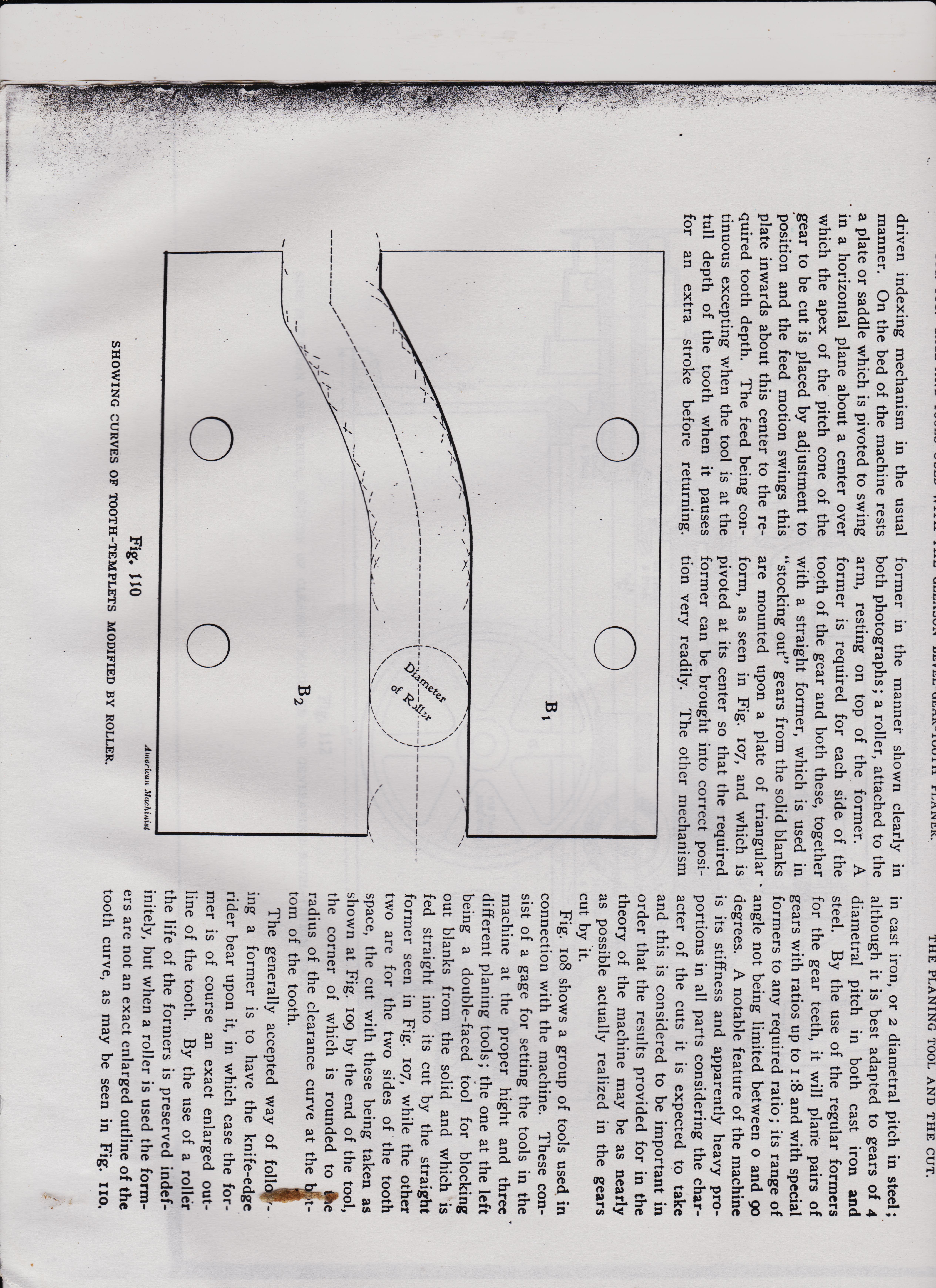
in cast iron, or 2 diametral pitch in steel; although it is best adapted to gears of 4 diametral pitch in both cast iron and steel. By the use of the regular formers for the gear teeth, it will plane pairs of gears with ratios up to :8 and with special formers to any required ratio ; its range of angle not being limited between o and 90 degrees. A notable feature of the machine is its stiffness and apparently heavy pro-portions in all parts considering the char-acter of the cuts it is expected to take and this is considered to be important in order that the results provided for in the theory of the machine may be as nearly as possible actually realized in the gears cut by it. Fig. Io8 shows a group of tools used in connection with the machine. These con-sist of a gage for setting the tools in the machine at the proper bight and three different planing tools the one at the left being a double-faced tool for blocking out blanks from the solid and which is fed straight into its cut by the straight former seen in Fig. 107, while the other two are for the two sides of the tooth space, the cut with these being taken as shown at Fig. 109 by the end of the tool, the corner of which is rounded to the radius of the clearance curve at the tom of the tooth. The generally accepted way of foil ing a former is to have the knife-edge rider bear upon it, in which case the former is of course an exact enlarged out-line of the tooth. By the use of a roller the life of the formers is preserved indefinitely, but when a roller is used the formers are not an exact enlarged outline of the tooth curve, as may be seen in Fig. no.
driven indexing mechanism in the usual manner. On the bed of the machine rests a plate or saddle which is pivoted to swing in a horizontal plane about a center over which the apex of the pitch cone of the gear to be cut is placed by adjustment to position and the feed motion swings this plate inwards about this center to the re-quired tooth depth. The feed being continuous excepting when the tool is at the full depth of the tooth when it pauses for an extra stroke before returning.
former in the manner shown clearly in both photographs ; a roller, attached to the arm, resting on top of the former. A former is required for each side. of the tooth of the gear and both these, together with a straight former, which is used in "stocking out" gears from the solid blanks are mounted upon a plate of triangular form, as seen in Fig. 107, and which is pivoted at its center so that the required former can be brought into correct posi-tion very readily. The other mechanism
American Machinist
Fig. 110 SHOWING CURVES OF TOOTH-TEMPLETS MODIFIED BY ROLLER.
>has the swinging motion in a horizontal plane given to it by the feed motion al-ready referred to, but it also swings in a vertical plane about a center which inter-sects the other center lines and this ver-tical swinging motion is controlled by the
accommodate gears of various proportions having hubs of unusual length. also a clear space in front of the or those There is blank so that where a hub happens to ex-
AMERICAN MACHINIST
< A tool-carrying head reciprocates upon a slide mounted upon the saddle referred to and is moved by a crank and connection best seen in Fig. 107. This slide not only tend beyond the apex of the gear itself the machine is still able to handle such a gear. On the spindle that holds the work there is the usual master wheel by which the divisions are made and this is turned automatically at the proper times by a friction-
FIG. 108. GAGE AND TOOLS USED WITH THE GLEASON BEVEL-GEAR-TOOTH PLANER. 29-1059
is for automatically returning the tool to the top of a tooth space at a rapid rate, indexing the blank and again starting the feed motion, all of which goes on without attention until the wheel is finished and the machine automatically stops itself. These machines are of course built in a variety of sizes, but the one shown is called the 24-inch machine and is for planing gears as coarse as 'IA diametral pitch American Machinist
Fig. 109 THE PLANING TOOL AND THE CUT.
in cast iron, or 2 diametral pitch in steel; although it is best adapted to gears of 4 diametral pitch in both cast iron and steel. By the use of the regular formers for the gear teeth, it will plane pairs of gears with ratios up to :8 and with special formers to any required ratio ; its range of angle not being limited between o and 90 degrees. A notable feature of the machine is its stiffness and apparently heavy pro-portions in all parts considering the char-acter of the cuts it is expected to take and this is considered to be important in order that the results provided for in the theory of the machine may be as nearly as possible actually realized in the gears cut by it. Fig. Io8 shows a group of tools used in connection with the machine. These con-sist of a gage for setting the tools in the machine at the proper bight and three different planing tools the one at the left being a double-faced tool for blocking out blanks from the solid and which is fed straight into its cut by the straight former seen in Fig. 107, while the other two are for the two sides of the tooth space, the cut with these being taken as shown at Fig. 109 by the end of the tool, the corner of which is rounded to the radius of the clearance curve at the tom of the tooth. The generally accepted way of foil ing a former is to have the knife-edge rider bear upon it, in which case the former is of course an exact enlarged out-line of the tooth. By the use of a roller the life of the formers is preserved indefinitely, but when a roller is used the formers are not an exact enlarged outline of the tooth curve, as may be seen in Fig. no.
driven indexing mechanism in the usual manner. On the bed of the machine rests a plate or saddle which is pivoted to swing in a horizontal plane about a center over which the apex of the pitch cone of the gear to be cut is placed by adjustment to position and the feed motion swings this plate inwards about this center to the re-quired tooth depth. The feed being continuous excepting when the tool is at the full depth of the tooth when it pauses for an extra stroke before returning.
former in the manner shown clearly in both photographs ; a roller, attached to the arm, resting on top of the former. A former is required for each side. of the tooth of the gear and both these, together with a straight former, which is used in "stocking out" gears from the solid blanks are mounted upon a plate of triangular form, as seen in Fig. 107, and which is pivoted at its center so that the required former can be brought into correct posi-tion very readily. The other mechanism
American Machinist
Fig. 110 SHOWING CURVES OF TOOTH-TEMPLETS MODIFIED BY ROLLER.
AMERICAN-MACHINIST-1900
pg 1060-30 AMERICAN MACHINIST 1900
1060-30
where the path the center of the roller describes is the true curve, but the formers are a corrected curve generated by the cylindrical surface of the roller. means of the shafts and bevel gears as can be easily followed in the drawings, the short vertical shaft E3 passing up through the center of the machine about which all the principal motions take place. The part E, Figs. II1, 112 and 113, turns in a horizontal plane about the center of the machine. The overhead arm A turns in a vertical plane about the center 0, while at the same time it of course has the same motion in a horizontal plane as has arm A the motions of this bar being in fact iden-tical with the motions of the bar or slide
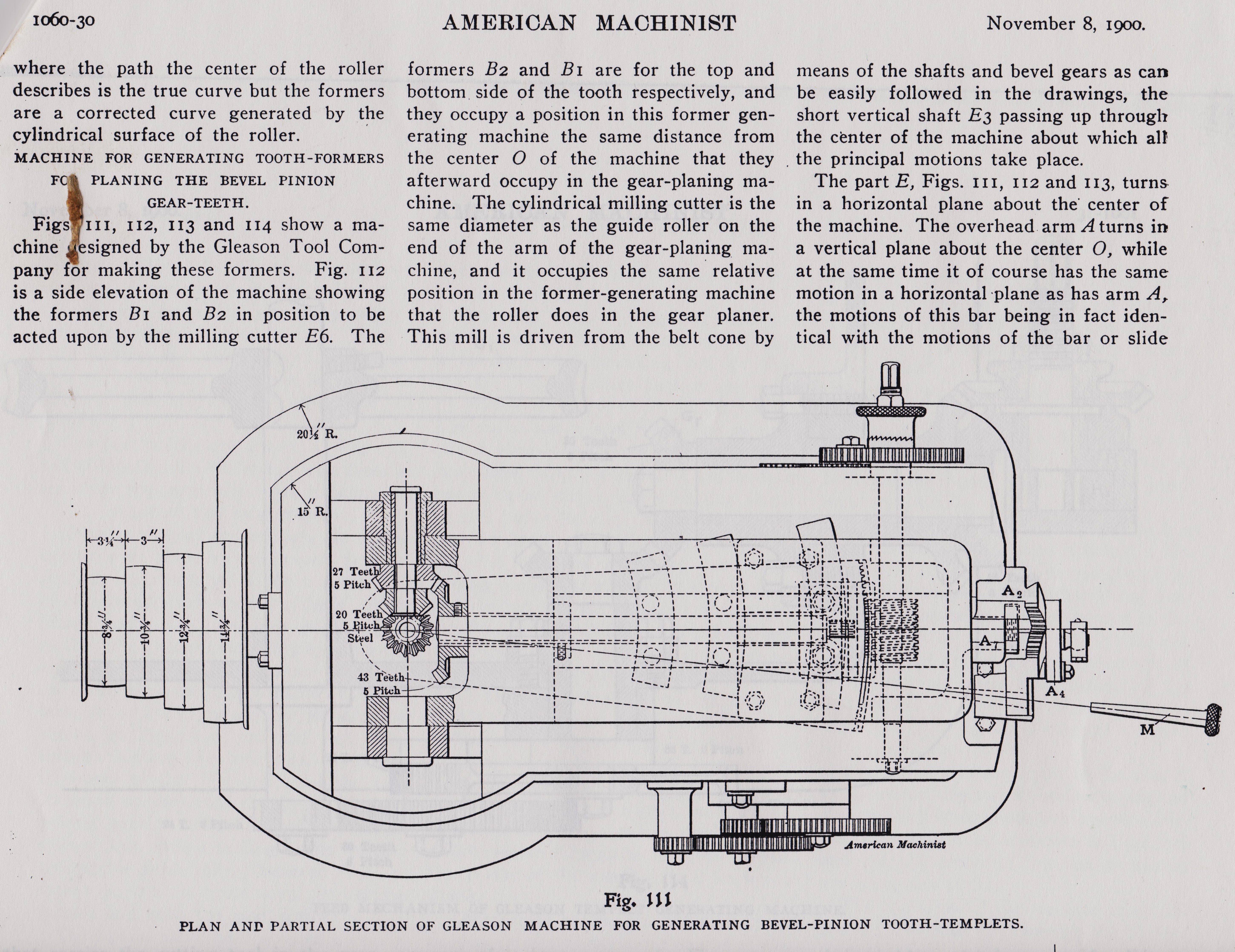
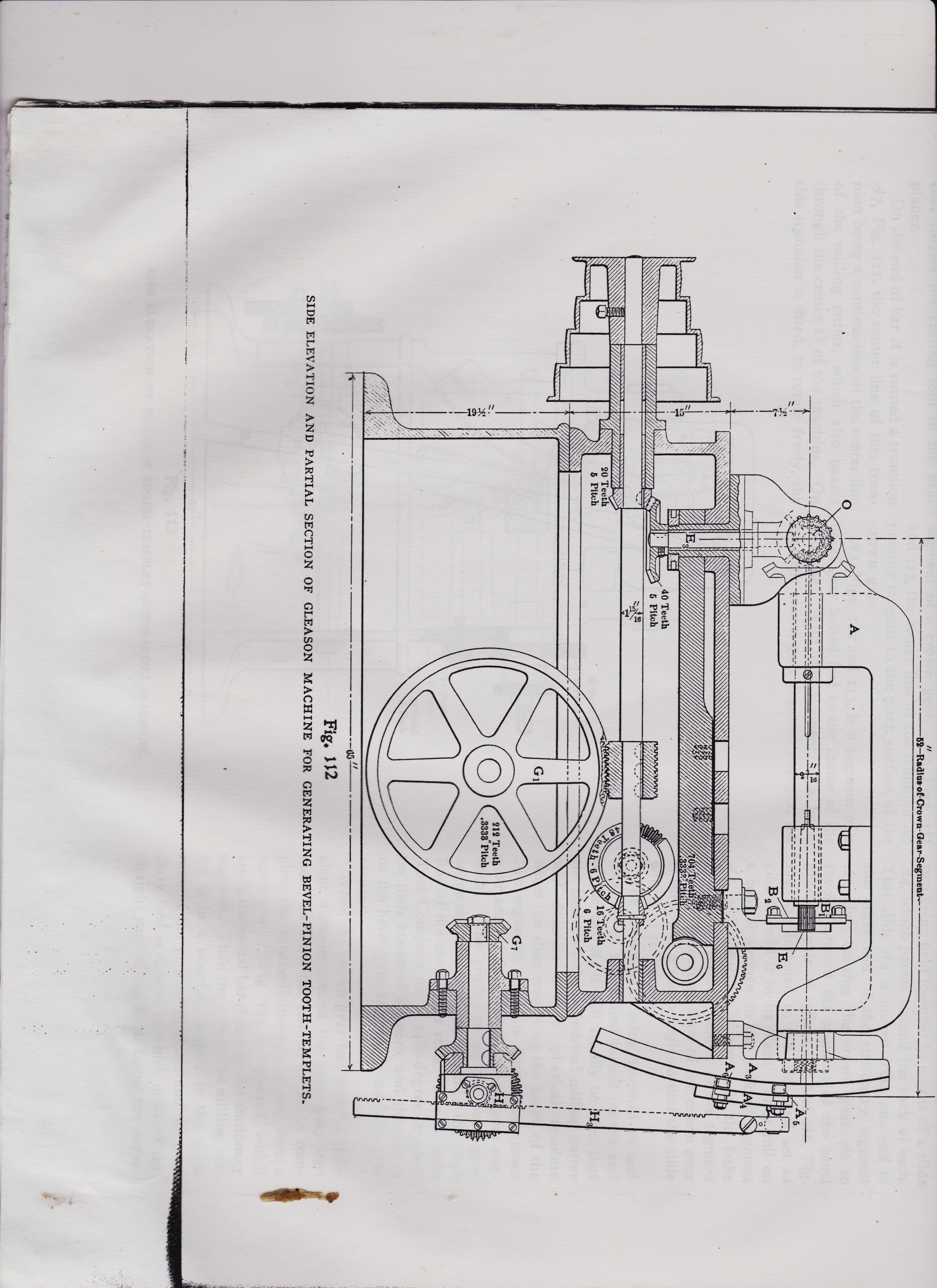
MACHINE FOR GENERATING TOOTH --FORMERS FC PLANING THE BEVEL PINION GEAR--TEETH. Figs HI' 112, 113 and 114
show a machine chine signed by the Gleason Tool Comftpany for making these formers.
Fig. 112 is a side elevation of the machine showing the formers 131 and B2 in position to be acted upon by the milling cutter E6. The formers B2 and B1 are for the top and bottom side of the tooth respectively, and they occupy a position in this former gen-erating machine the same distance from the center 0 of the machine that they afterward occupy in the gear-planing ma-chine. The cylindrical milling cutter is the same diameter as the guide roller on the end of the arm of the gear-planing ma-chine, and it occupies the same relative position in the former-generating machine that the roller does in the gear planer. This mill is driven from the belt cone by means of the shafts and bevel gears as can be easily followed in the drawings, the short vertical shaft E3 passing up through the center of the machine about which all the principal motions take place. The part E, Figs. II1, 112 and 113, turns in a horizontal plane about the center of the machine. The overhead arm A turns in a vertical plane about the center 0, while at the same time it of course has the same motion in a horizontal plane as has arm A the motions of this bar being in fact iden-tical with the motions of the bar or slide
27 Teeth, A 5 Pitch 4 20 Teeth 4----, Steel Al 43 te-eth 5 Pitch-
November 8, 1900
pg 1060-30 AMERICAN MACHINIST 1900
1060-30
where the path the center of the roller describes is the true curve, but the formers are a corrected curve generated by the cylindrical surface of the roller. means of the shafts and bevel gears as can be easily followed in the drawings, the short vertical shaft E3 passing up through the center of the machine about which all the principal motions take place. The part E, Figs. II1, 112 and 113, turns in a horizontal plane about the center of the machine. The overhead arm A turns in a vertical plane about the center 0, while at the same time it of course has the same motion in a horizontal plane as has arm A the motions of this bar being in fact iden-tical with the motions of the bar or slide
MACHINE FOR GENERATING TOOTH --FORMERS FC PLANING THE BEVEL PINION GEAR--TEETH. Figs HI' 112, 113 and 114
show a machine chine signed by the Gleason Tool Comftpany for making these formers.
Fig. 112 is a side elevation of the machine showing the formers 131 and B2 in position to be acted upon by the milling cutter E6. The formers B2 and B1 are for the top and bottom side of the tooth respectively, and they occupy a position in this former gen-erating machine the same distance from the center 0 of the machine that they afterward occupy in the gear-planing ma-chine. The cylindrical milling cutter is the same diameter as the guide roller on the end of the arm of the gear-planing ma-chine, and it occupies the same relative position in the former-generating machine that the roller does in the gear planer. This mill is driven from the belt cone by means of the shafts and bevel gears as can be easily followed in the drawings, the short vertical shaft E3 passing up through the center of the machine about which all the principal motions take place. The part E, Figs. II1, 112 and 113, turns in a horizontal plane about the center of the machine. The overhead arm A turns in a vertical plane about the center 0, while at the same time it of course has the same motion in a horizontal plane as has arm A the motions of this bar being in fact iden-tical with the motions of the bar or slide
27 Teeth, A 5 Pitch 4 20 Teeth 4----, Steel Al 43 te-eth 5 Pitch-
November 8, 1900
American-Machinist-Nov-8-1900-bot-The-Gleason-Bevel-Gear-Toot-Planer-Machine-tooth-tracer-cutter
https://antiquemachinery.com/images-American-Machinist-Nov-8-1900-bot-The-Gleason-Bevel-Gear-Toot-Planer/American-Machinist-Nov-8-1900-pg-31-1061-top.jpeg
https://antiquemachinery.com/images-American-Machinist-Nov-8-1900-bot-The-Gleason-Bevel-Gear-Toot-Planer/American-Machinist-Nov-8-1900-pg-31-1061-top.jpeg
AMERICAN-MACHINIST-1900
pg 1060-31 AMERICAN MACHINIST 1900
1060-31
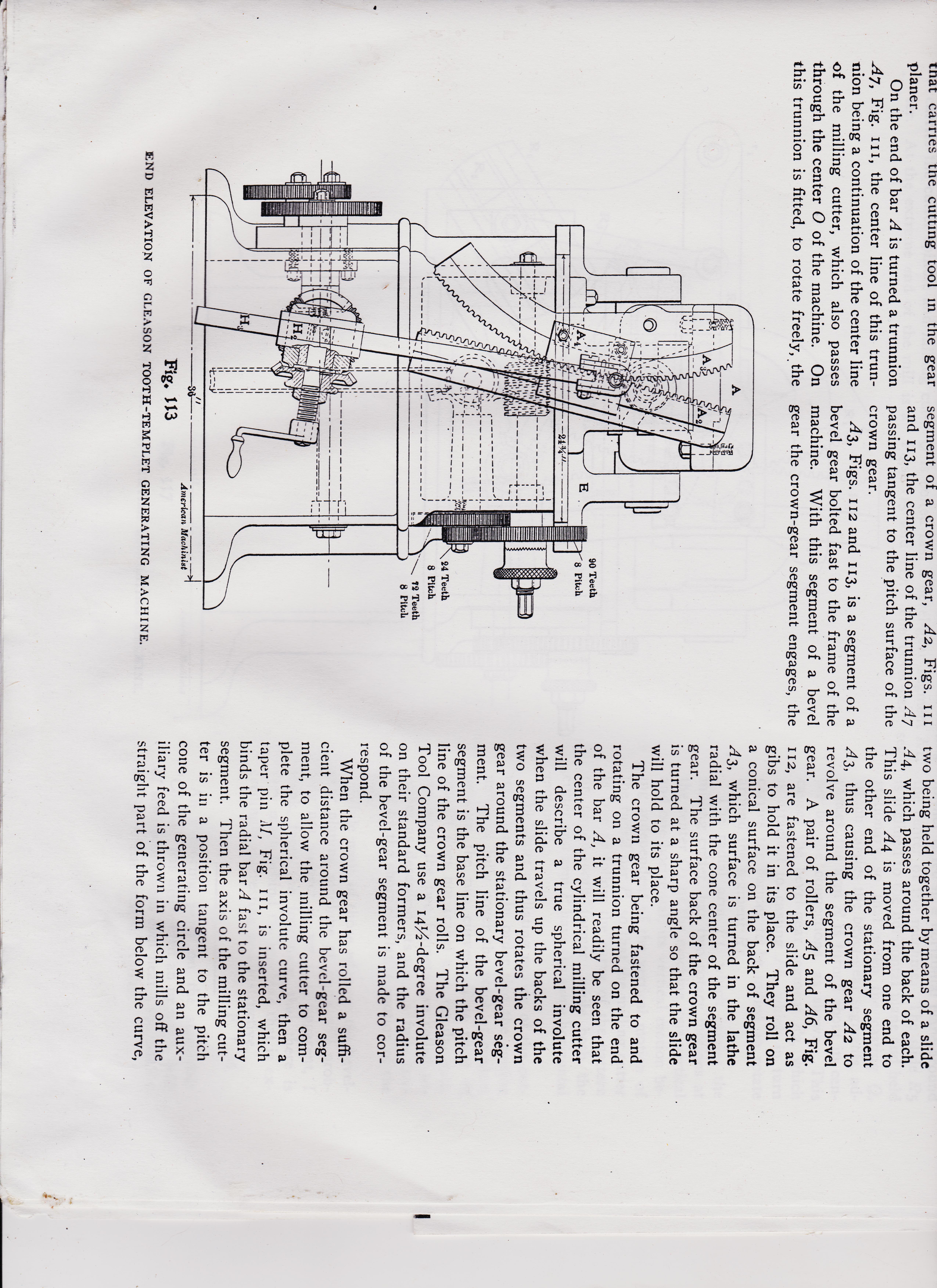
tnat carries the cutting tool in the gear planer. On the end of bar A is turned a trunnion A7, Fig. III, the center line of this trun-nion being a continuation of the center line of the milling cutter, which also passes through the center 0 of the machine. On this trunnion is fitted, to rotate freely, the segment of a crown gear, A2, Figs. III and 113, the center line of the trunnion A7 passing tangent to the pitch surface of the crown gear. A3, Figs. 112 and 113, is a segment of a bevel gear bolted fast to the frame of the machine. With this segment of a bevel gear the crown-gear segment engages, the
90 Teeth 8 Pitch
24 Teeth 8 Pitch /2 Teeth 8 Pitch
Fig. 113 END ELEVATION OF GLEASON TOOTH-TEMPLET GENERATING MACHINE.
two being held together by means of a slide A4, which passes around the back of each. This slide A4 is moved from one end to the other end of the stationary segment A3, thus causing the crown gear A2 to revolve around the segment of the bevel gear. A pair of rollers, A5 and A6, Fig. 112, are fastened to the slide and act as gibs to hold it in its place. They roll on a conical surface on the back of segment A3, which surface is turned in the lathe radial with the cone center of the segment gear. The surface back of the crown gear is turned at a sharp angle so that the slide will hold to its place. The crown gear being fastened to and rotating on a trunnion turned on the end. of the bar A, it will readily be seen that the center of the cylindrical milling cutter will describe a true spherical involute when the slide travels up the backs of the two segments and thus rotates the crown gear around the stationary bevel-gear seg-ment. The pitch line of the bevel-gear segment is the base line on which the pitch line of the crown gear rolls. The Gleason Tool Company use a I41/2-degree involute on their standard formers, and the radius of the bevel-gear segment is made to cor-respond. When the crown gear has rolled a suffi-cient distance around the bevel-gear seg-ment, to allow the milling cutter to com-plete the spherical involute curve, then a taper pin :11, Fig. III, is inserted, which binds the radial bar A fast to the stationary segment. Then the axis of the milling cut-ter is in a position tangent to the pitch cone of the generating circle and an aux-iliary feed is thrown in which mills off the straight part of the form below the curve,
pg 1060-31 AMERICAN MACHINIST 1900
1060-31
tnat carries the cutting tool in the gear planer. On the end of bar A is turned a trunnion A7, Fig. III, the center line of this trun-nion being a continuation of the center line of the milling cutter, which also passes through the center 0 of the machine. On this trunnion is fitted, to rotate freely, the segment of a crown gear, A2, Figs. III and 113, the center line of the trunnion A7 passing tangent to the pitch surface of the crown gear. A3, Figs. 112 and 113, is a segment of a bevel gear bolted fast to the frame of the machine. With this segment of a bevel gear the crown-gear segment engages, the
90 Teeth 8 Pitch
24 Teeth 8 Pitch /2 Teeth 8 Pitch
Fig. 113 END ELEVATION OF GLEASON TOOTH-TEMPLET GENERATING MACHINE.
two being held together by means of a slide A4, which passes around the back of each. This slide A4 is moved from one end to the other end of the stationary segment A3, thus causing the crown gear A2 to revolve around the segment of the bevel gear. A pair of rollers, A5 and A6, Fig. 112, are fastened to the slide and act as gibs to hold it in its place. They roll on a conical surface on the back of segment A3, which surface is turned in the lathe radial with the cone center of the segment gear. The surface back of the crown gear is turned at a sharp angle so that the slide will hold to its place. The crown gear being fastened to and rotating on a trunnion turned on the end. of the bar A, it will readily be seen that the center of the cylindrical milling cutter will describe a true spherical involute when the slide travels up the backs of the two segments and thus rotates the crown gear around the stationary bevel-gear seg-ment. The pitch line of the bevel-gear segment is the base line on which the pitch line of the crown gear rolls. The Gleason Tool Company use a I41/2-degree involute on their standard formers, and the radius of the bevel-gear segment is made to cor-respond. When the crown gear has rolled a suffi-cient distance around the bevel-gear seg-ment, to allow the milling cutter to com-plete the spherical involute curve, then a taper pin :11, Fig. III, is inserted, which binds the radial bar A fast to the stationary segment. Then the axis of the milling cut-ter is in a position tangent to the pitch cone of the generating circle and an aux-iliary feed is thrown in which mills off the straight part of the form below the curve,
American-Machinist-Nov-8-1900-bot-The-Gleason-Bevel-Gear-Toot-Planer-Machine-tooth-tracer-cutter
**************************************************
https://antiquemachinery.com/images-American-Machinist-Nov-8-1900-bot-The-Gleason-Bevel-Gear-Toot-Planer/American-Machinist-Nov-8-1900-pg-32-1061-top-ee.jpeg
https://antiquemachinery.com/images-American-Machinist-Nov-8-1900-bot-The-Gleason-Bevel-Gear-Toot-Planer/American-Machinist-Nov-8-1900-pg-32-1061-bot-Line-drawing-of-the-machine-side-and-partial-section-gears-work-are-machined-cut-how-the-machne-works-Mechanism--Gleason-Templet-Bevel-Pinion-Tooth-.jpeg

AMERICAN-MACHINIST-1900
pg 1060-32 AMERICAN MACHINIST 1900
1060-32
AMERICAN MACHINIST Teeth Pitch 20 Tedh 5 Pitch Steel 43 Teeth_' 5 Pitch
24 Teeth-8 Pitch 72 T- 8 Pitch V4
90 Teeth- 8 Pitch V6
T Worm Wheel 30 Teeth Y'lpitch
Fig. 115 American Machinist
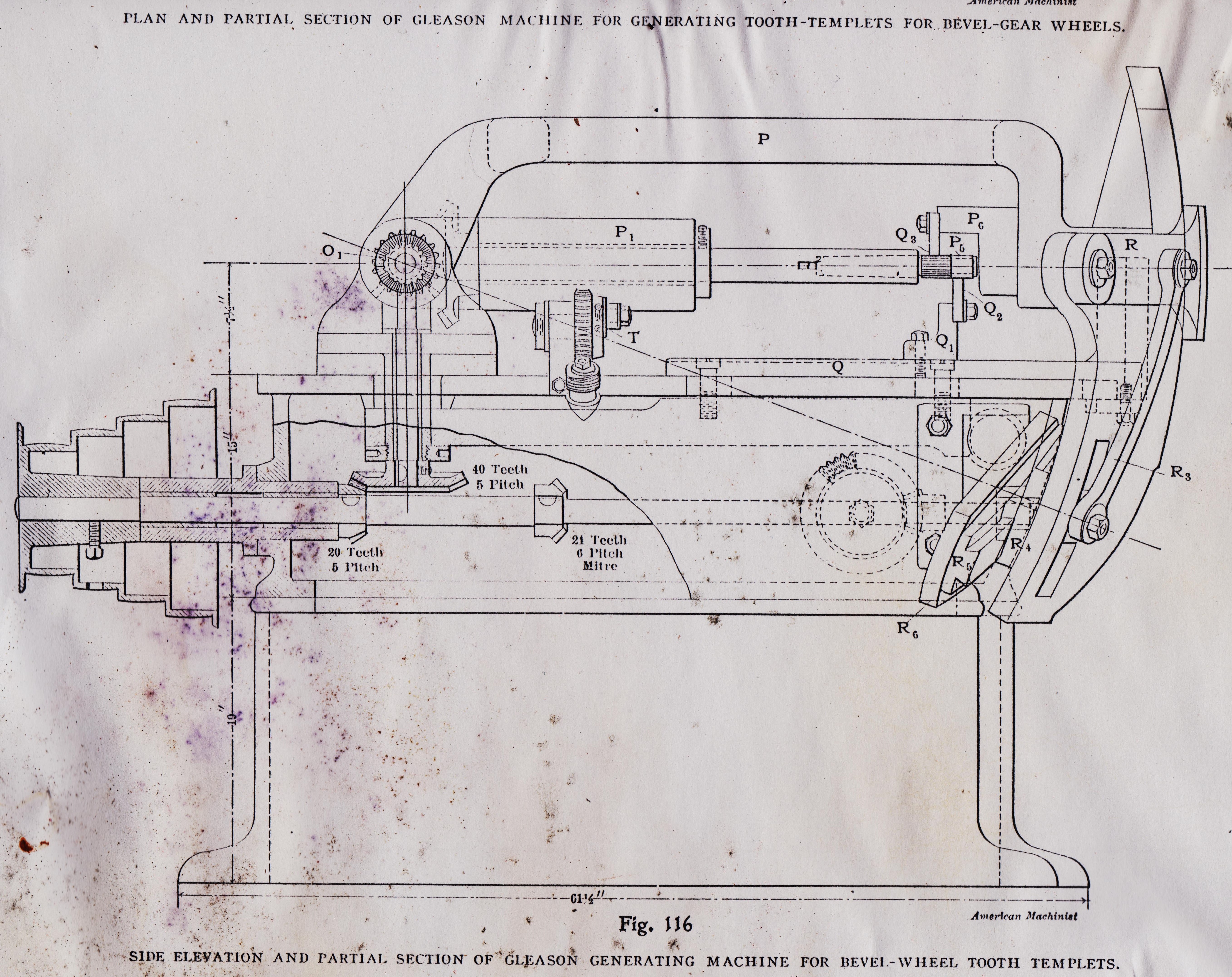
PLAN AND PARTIAL SECTION OF GLEASON MACHINE FOR GENERATING TOOTH-TEMPLETS FOR BEVEL-GEAR WHEELS. AI
pg 1060-32 AMERICAN MACHINIST 1900
1060-32
AMERICAN MACHINIST Teeth Pitch 20 Tedh 5 Pitch Steel 43 Teeth_' 5 Pitch
24 Teeth-8 Pitch 72 T- 8 Pitch V4
90 Teeth- 8 Pitch V6
T Worm Wheel 30 Teeth Y'lpitch
Fig. 115 American Machinist
PLAN AND PARTIAL SECTION OF GLEASON MACHINE FOR GENERATING TOOTH-TEMPLETS FOR BEVEL-GEAR WHEELS. AI
American-Machinist-Nov-8-1900-The-Gleason-Bevel-Gear-Toot-Planer-Machine-tooth-tracer-cutter pg.32
************************6***pg 32***********************
https://antiquemachinery.com/images-American-Machinist-Nov-8-1900-bot-The-Gleason-Bevel-Gear-Toot-Planer/American-Machinist-Nov-8-1900-pg-32-1061-top-ee.jpeg
https://antiquemachinery.com/images-American-Machinist-Nov-8-1900-bot-The-Gleason-Bevel-Gear-Toot-Planer/American-Machinist-Nov-8-1900-pg-32-1061-bot-Line-drawing-of-the-machine-side-and-partial-section-gears-work-are-machined-cut-how-the-machne-works-Mechanism--Gleason-Templet-Bevel-Pinion-Tooth-.jpeg
32 t
https://antiquemachinery.com/images-American-Machinist-Nov-8-1900-bot-The-Gleason-Bevel-Gear-Toot-Planer/American-Machinist-Nov-8-1900-pg-33-1061-top.jpeg
33 b
https://antiquemachinery.com/images-American-Machinist-Nov-8-1900-bot-The-Gleason-Bevel-Gear-Toot-Planer/American-Machinist-Nov-8-1900-pg-33-1061-bot--ee.jpeg

AMERICAN-MACHINIST-1900
pg 1060-33 AMERICAN MACHINIST 1900
1060-33
AI
pg 1060-33 AMERICAN MACHINIST 1900
1060-33
AI
American-Machinist-Nov-8-1900-The-Gleason-Bevel-Gear-Toot-Planer-Machine-tooth-tracer-cutter pg.32
************************6**************************