Ask not for whom the bell tolls for......
Jan 29 1887
New Radial Drilling Machine.
SHAPERS, ENGINE LATHES AIIRILLLS
TWENTY IN. LEVER DRILL.
LODGE, DAVIS & CO. CINCINNATI, OHIO.
E. COULD & EBERHARDT, C0 NEWARK, N. J
E.E. GARVIN & CO 139 & 141 CENTRE ST., NEW YORK, Manufacturers of MACHINISTS' TOOLS Small Automatic Miller WITH ARM.
The Machine shown in cut is designed for rapid and convenient milling of small work. .

AM
A JOURNAL FOR MACHINISTS, ENGINEERS, FOUNDERS, BOILER MAKERS, PATTERN MAKERS, AND BLACKSMITHS,
VOL. 10, No. 4 WEEKLY. NEW YORK, JANUARY 22, 1887.
COPYRIGHT 1887, BY AMERICAN MACHINIST PUBLISHING COMPANY. For Sale Everywhere by Newsdealers. 5 82.50 per Annum. t SINGLE COPIES, a CENTS. ENTERED AT POST OFFICE, NEW YORK, AS SECOND CLASS MATTER. New Radial Drilling Machine.
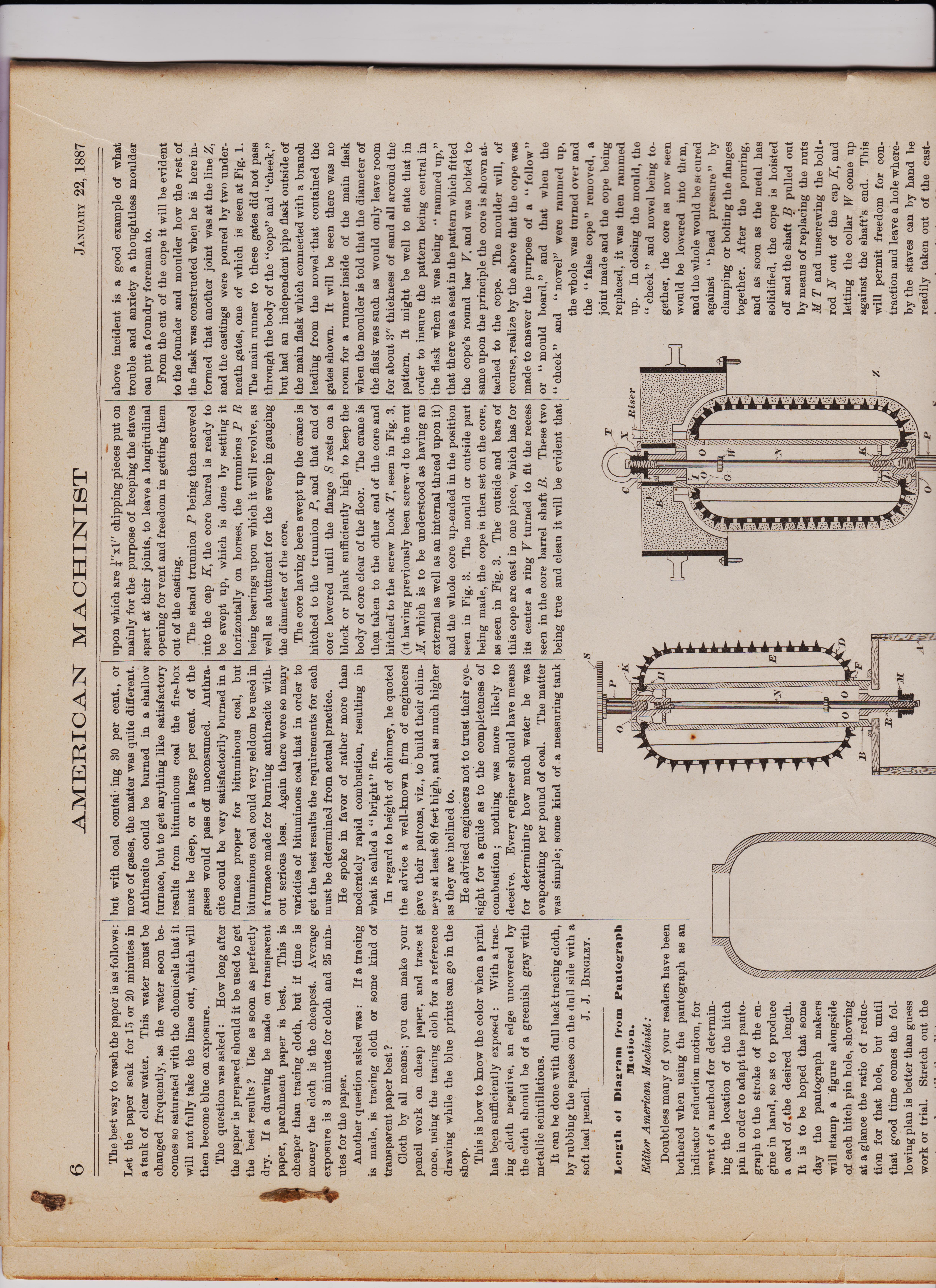
The machine illustrated herewith has a quarter-circle base, of unusual size, for the accommodation of large work. The outside pillar or support is moved around the circle by means of rack and pinion, in a way clearly shown in the engraving ; this pillar can, when required, be bolted rigidly to the base, or it can be removed to admit work otherwise too large to be admitted under the spindle. The arm has a bearing on the main column 32 inches in length, and is strongly ribbed on the top. The spindle frame is moved along by means of a crank, which enables the operator to stand at the spindle while bringing it to the desired position. The column which carries the arm, driving gear, frame, etc., is bored and fitted over a stationary stump, bolted fast to the sole plate; this stump has sufficient length of bearing to prevent column from swaying, and is provided with an adjustable pivot bearing upon an elastic diaphragm in the column, which, when the bolts in the flange at the lower end of column are slackened, takes the weight of the machine off the flange bearing, and allows the column with arm, etc., to revolve easily the entire circle. For ordinary drilling the bolts in flange need not be tightened,but when extraordinary rigidity
bolted Mtn to the mule pate; tuus stump has sufficient length of bear-ing to prevent column from swaying, and is provided with an adjustable pivot bearing upon an elastic dia-phragm in the column, which, when the bolts in the flange at the lower end of column are slackened, takes the weight of the machine off the flange bearing, and allows the column with arm, etc., to revolve easily the entire circle. For ordinary drilling the bolts in flange need not be tight-ened,but when extraordinary rigidity is required a partial turn of the wrench will bind the column fast to the sole plate. The sleeve which carries the arm and gear frame is fitted snugly to the column and may be raised and lowered by power, and is provided with clamping bolts. The table has both horizontal and vertical faces, and is provided with T slots, all planed. The counter shaft consists of a frame with horizontal shaft and T and L pulleys, and a pair of cut miter gears to connect with vertical shaft at center of top of column. The spindle, feed screw, elevating screw andall shafts are made of machinery steel, and the feed worm is made of the best tool steel and hardened ; all thrust bearings are provided with phosphor bronze washers. The machine illustrated has a column 15 inches diameter and 91 feet in height. The radius of arm is 8 feet, giving a possible distance of 6 feet 10 inches from base to end of spindle. The greatest distance from floor to end of spindle is 7i feet. The total height of machine exclusive of countershaft is 11 feet 5 ina'hes, or including countershaft, 13 feet. The height of table from base is 25 inches, the-Itt of table being 28 inches square. The table as planed T slots on the top and on two sides. The spindle is 21- inches diameter, with hole " Morse taper." The traverse Of spindle is, 20 inches. The weight of this ' machine is about 15,000 pounds'. This machine is manufactured by the Uni-versal 'Radial Drill Company, Cincinnati, Ohio.
New Radial Drilling Machine.
equal to every emergency. He will be called upon to produce the most unheard of machinery. Whatever the class of work, he must do good work, and he must do it ac-cording to promise. A safe rule to begin with is, never indorse for any one and never ask for indorsement. Buy at headquarters, and for cash if possible. Allow your creditor to draw on you through the bank. You will probably get longer time by doing so. Never return a draft--hold it and pay as soon as you can. Use brains in designing new ma-chines. Adopt old styles if simpler, rather than new ones that are com-plex. Use plenty of iron—too much is just right. Treat all customers alike, even your worst enemy, and the man who parleys half a day and goes away without ordering any-thing you may get later. Hire only good workmen. Think a couple of times before hiring a dis-charged man back again ; he will get even with you or ahead. Pay higher wages than other shops ; you can afford it. Never allow a man to be dissatisfied with hi's pay. Keep a limited number of apprentices and teach them everything in the shop, and when in need of a foreman make one of an apprentice rather than a stranger. The writer once said to an apprentice, " Young man, do your best, you don't know what may happen here in ten years, you
************************************************************************************************
4 Starting a Machine Shop. design it so as to build on afterward. If located in a small country town few tools BY C. W. CRAWFORD. will be required at first, depending on the surroundings A 36" and 20" lathes of good Nearly every machinist has an ambition to make, a 30"x30"x8' planer, a 36" back-geared, become a foreman or proprietor of a ma- self-feed drill and a small drill, a pattern-chine shop of some kind. It is much easier maker's lathe, a lot of machinists' small tools to succeed in the former than the latter and tool grinder, an engine and boiler, line capacity, but to be a successful proprietor a shaft and pulleys, etc., will be good outfit. In
man ought to have some experience as fore-man. Most shops are established for some particular kind of work,'generally local work, specialties being taken up afterward. This is probably the best plan, because if a shop can hold its own, or make money on local trade, it is safer to risk special work after having some experience, The amount of capital required need not be large, and can be saved in a few years if a man has only the will to do it. It is'generally safe to follow the advice of Horace Greeley, and go West. There are plenty of towns yet wanting ma-chine shops. In choosing a location it is proper to ask the citizens to donate a site and building ; very few towns will refuse this equest. It is besfto build a brick shop, and
addition, a face-plate lathe will be needed. This tool can be made cheaper than it can be bought, consisting, according to Chordal, of a few gears and pulleys, a belt, and a hole in the ground, a set of blacksmith tools and forge, and a foundry outfit consisting of a cupola made of the shell of a 42" boiler, a few ladles, flasks and some sand completes the layout. • The head of such a shop must be a machinist, a good workman, and a man of indomitable will and perseverance, and its success will depend on his energy, integrity and financial ability. Very few machinists combine all of these qualities in addition to their mechanical ability, and hence more fail than succeed. The man who runs a pro-vincial shop must be full of expedients and charged man back again ; he will get even with you or ahead. Pay higher wages than other shops ; you can afford it. Never allow a man to be dissatisfied with his pay. Keep a limited number of apprentices and teach them everything in the shop, and when in need of a foreman make one of an apprentice rather than a stranger. The writer once said to an apprentice, " Young man, do your best, you don't know what may happen here in ten years, you may be at the head of this shop." That boy is now foreman of the shop, and is a success. Paddle your oven canoe if possible, but an agreeable partner is desirable. Two are com-pany, but, bear in mind, three are a riot. A partner must not be of the same trade as yourself, or better, no mechanic at all, but a good office man, who can also talk machinery. Locate where there is a good local trade, but work up a shill iisg trade as soon as possible. :this is what builds up a town ; local trade is simply swapping dollars, as icr as profit to that locality is con_ cerned. Avoid strikes by discharging all chronic agitators. Good men can always be kept at work by pay-ing good wages. Invest your money in extending your business, and after fifty years of age, let your foreman run the shop and make yourself comfortable.
Massachusetts Institute of Technology., We are in receipt of the Twenty-Secoli Annual Catalogue of the Massachusetts In tute of Technology, of Boston. It contain a list of the officers and students, and a stag ment of the courses of instruction ; also a list of the Alumni. It is a book of more than 160 pages ; giving very complete information re-garding the workings of the Institute. The foundation of the Institute, and its subse-quent growth are matters that will be found interesting reading. The following in rela-tion to mechanical engineering, which we copy from the catalogue, will show the scope of the school in this direction : The course aims to equip the student with


AMERICAN-MACHINIST-1887-page 2
.
MACHINIST JANUARY 22, 1887
such training in pure and applied mathe-matics as shall qualify him to deal with the engineering problems of his profession from the most favorable standpoint. It attempts by instruction, both theoretical and practical, to acquaint him with engineering practice, and to give him a proper groundwork upon which to base a professional career. The more strictly professional work of the course may be classified as follows : 1. Mathematics, physics, and applied me-chanics, given outside the departmen.° ; the last including the study of, and practice in sting the strength of materials. . Recitation-room work of the department oper, beginning with a study of the prin.- les of mechanism, the construction of gear_ eth, etc.. and continued by courses on ma-ne tools and cotton machinery. Courses e given on the slide-valve and link, ther-modynamics, theory of the steam engine, and on steam boilers. The fourth year instruc-tion includes such mechanical engineering *subjects as dynamometers, governors, fly-wheels, springs, relative effect of reciprocat-ing parts, balancing of engines, injectors, steam-pumps, cylinder condensation, hy-draulics and hydraulic motors, etc. An option is given among courses on marine engineering, locomotive construction, and mill engineering. 3. Drawing-room work. The students in the second year make work-drawings from measurements, and the drawings necessary in connection with the course in mechanism and gear construction. In the third year they make detail and assembly drawings from machinery, and this is followed by mechanism designs, and boiler drawings. In the fourth year a course in machine designs is given. 4. Shop-work, including carpentry, pat-tern-making forging, chipping, filing, and machine-tool work. 5. Mechanical engineering laboratory work. This begins with drill in steam-engine tests in the second terms of the third year, and is continued throughout the fourth year, includ-ing tests of boilers, pumps, power, etc., and a large amount of investiga ion. Following this the 'course of studies are given in detail ; they seem to us to be very complete. The course in civil engineering, mining en-gineering, electrical engineering, chemistry, &c., &c , are equally well explained. We should say that the catalogue would be in-structive to any student in the direction of applied science. Condition and Prospects of the Machinery Business.
LETTERS FROM PROMINENT ESTABLISHMENTS TO THE " AMERICAN MACHINIST."
orders we have filled, during the coming year. We find that steam users are appreciating the superior points of water tube boilers, and are expressing their appreciation in the very practical way of giving us the preference, when placed on an equal footing with other manufacturers of the same class of boilers. This, of course, has encouraged us to con-stantly increase our facilities for manufacture, and to maintain the high standard of work-manship and material with which we origi-nally started out in the manufacture of these boilers. We are therefore in a position to look forward with great encouragement to the coming year, and expect to be able to make a still better report at the close of 1887. Coffin &Leighton (Machinists' Steel Scales). Syracuse, N. Y., write us : Our trade for 1886, our first year, has been good. Our scales are giving complete satis-faction. The prospects for the coming year are very favorable.
W. P. Davis, (Machine Tools),North Bloom field, N. Y., writes us :
Business for 1886 has been quite satisfac-tory with me ; while we have not d ne a large busine-s I can see we are steadily gaining ground as we become better known, and we see a decided change for the better in the past two months, and think we have every reason to look for quite an increase of business in the spring. We have had quite a limited ex-port trade this season, but could not look for much as we have not advertised abroad the past year. We are just finishing a lot of one hundred and twelve machines, which we have made in one lot, 56 being our 20-inch drill on which we are having a fine trade. We are just finishing a new grinding machine for grinding long strips of steel,and bringing them square and true, the machine working auto-matic. We have made some improvements this year by putting in new machinery, etc. We now heat our machine shop and foundry by exhaust steam pipes overhead, and it works well. Have also just finished our new office building which is separate from the main buildings, and find it much better in every respect, not only being clean but free from any jar whatever. It is also light. From past experience we think any one will find it a much better way when it is possible to have office separate from main building. We have turned our old office into a tool room, which makes a very satisfactory addition to our ma-chine room. We continue to use natural gas, and it is very satisfactory, both for fuel and lights. We have run full time the past year and have had no ti ouble with help in any way, and believe much of the labor trouble might be avoided were the employers more ready to look after the interests of their em-ployees before they had reason to complain. When they know ' on look out for their inter-
the world, some of our recent shipments being to Germany, Australia, New Zealand, etc. ,
and we think there is a prospect of our foreign trade increasing. L. S. Starrett (Fine Tools for Machinists), Athol, Mass. , writes us : We have' been so busy moving and getting settled in our new shop that we have had little time to answer your inquiry relating to business prospects. Will now say that our business dur-ing the past year has been better than ever be-fore. The increasing demand for our tools has been such as to compel us to increase our manufacturing facilities. This we have done by taking possession of our new shop, con-taining 8,640 square feet of floor room, high-posted, well lighted, fitted up with modern improvements and the best of tools, driven by a 60 horse-power wheel (although this is more than we at present require), and we shall be better than ever before prepared to fill our constantly-increasing orders. We are anticipating a greatly-increased trade for the year to come, and shall add new machinery from time to time as our business require-ments may demand. A few days since we were pleased by re-ceiving a diploma from Sweden, signed by the Crown Prince, Gustaf, for excellence of our fine tools on exhibition there. We have several new and improved tools that we shall soon add to our list, and such as we believe will command large sales.
J. M. Allen, President Hartford Steam Boiler Inspection and Insurance Company, Hartford, Conn., writes us : In reply to your favor, inquiring about the business of this company for the past year, I will say: The business of the company has been larger by far than that of any previous year, and the outlook for business the com-ing year was never more encouraging.
The Dwight Slate Machine Company (Ma chinery and Tools), Hartford, Conn., write us . The year 1886 opened with prospects of good business, and orders came in freely in January and February. During the spring and early summer months business was quite light, but since July has shown steady in crease the year closing more promising than 1885. During the year we have brought out some new tools—two and four spindle drills, with novel driving arrangements, consisting of single belt and tightening appliance; also a filing machine for handling hand files by power. Have also purchased the tools, pat-terns and fixtures of the Ballou Manufactur-ing Company, of this city, and shall continue the manufacture of their fine precision engine lathes, bench lathes, and the numerous VISIT1ViT1C1 A ftfLith IT1Mli Et_
The National Pipe Bending Co. , (Feed-Water Heaters and Iron, Brass and Copper Coils), New Haven, Conn., write us : Our business for 1886 has shown a very gratifying increase over that of the previous years. We have added two new machines to our coiling department, and are now able to make larger coils than before. The last four months of the year has given us a large num-ber of orders, and we have worked some over-time and added to our help. The price of material is going up some, but labor remains the same as in 1885. The demands for coils of iron and brass since July has exceeded that of any former year. The outlook for 1887 is very good.
Vanderburgh, Wells & Co. (Pattern Letters and Printers' Materials), 18 Dutch st., New York, write us :
Although our business for the year 1886 is slightly more in volume than for the year before, this gain was all in the earl v months of the year. Since the labor troubles of the country became serious in the spring orders have been to a great extent, confined to what our customers could not get along without ; showing that very few purchases were made with a view to the enlargement of old establishments, or toward starting new ones. The prices for our goods are a little firmer than they were a year ago, and the general prospect seems fair, although there is not quite so confident feeling as there should be. No change in rate of wages to report, and prices of what we buy much the same as they were a year ago. We have added to manufacturing facilities during the year, but not to a great extent.
The Muller Machine Tool Company, Cin-cinnati, O., write us : We commenced business last April with an entire new outfit, comprising the latest and most improved tools manufactured. At present we make a specialty of 16" engine lathes, beds of any desired length. We have furnished this tool to several of the largest machine shops in this city, and have received orders from all parts of the country for the same. We make it an object to build this tool as fine and accurate as can be made. Prices have been and are extremely low. The outlook for 1887 seems bright, and we hope may terminate in a general business improvement over 1886. We have had all we can do since we started.
The Variety Machine Company (Ratchet and Worm Drill Stocks), Warsaw, N. Y., write us :
complete. The course in civil engineering, mining en-gineering, electrical engineering, chemistry, &c., &c , are equally well explained. We should say that the catalogue would be in-structive to any student in the direction of applied science. Condition, and Prospects of the Machinery Business.
LETTERS FROM PROMINENT ESTABLISHMENTS TO THE AMERICAN MACHINIST."
Hewes & Phillips Iron Works (Steam En-gines, Boilers and Machinists' Tools), Newark, N. J., write us : The volume of business transacted by us during the year 1886 has been unusually large, showing a decided improvement over that of the year 1885. Prices received for our products have, however, been very un satisfactory, but we are happy to report that they are materially improving and with a prospect of a still further advance. During the past year we have put in a large number of new tools, and improved our equipment and organization in every department. The growth of our Corliss engine business has been of the most satisfactory character, having built about 50 during the year 1886, ranging in sizes from 50 up to 400 horse-power. We now have in course of construction engines for the following parties : One 250 horse-power Corliss engine, for Newark Elec-tric Light and Power Co. ; one 150 horse-power, for Soh mer & Co., piano manufac-turers, of New York; one 75 horse-power, for Claus Lipsius Brewery, Brooklyn ; one 60 horse-power, New York Preservative Co. ; one 60 horse-power, Judge Addison Brown ; and two, of 250 and 200 horse-power re-spectively, for Atchison, Topeka and Santa Fe Railroad ; also several others for different sections of the country. We are also execut-ing a large order for planers, shapers and Blotters for the above railroad ; also con-structing a fine plant of ten Otis steel boil-ers, of 120 horse-power each, for the Clark Mile End Spool Cotton Co. The above con-tracts, together with a large amount of other miscellaneous work, make us extremely busy, and we are now running nights. The pros-pects for the year 1887 are most flattering, and we look for a large and profitable busi-ness. The National Water Tube Boiler Company, New Brunswick N. J., write us : We are much gratified, in looking over our business of the past year, to note its growth and extent. We have had a large increase over that of the previous year, and, with the present indi-cations, we expect to double the number of omitting wiiicn is separate rrom tne main buildings, and find it much better in every respect, not only being clean but free from any jar whatever. It is also light. From past experience we think any one will find it a much better way when it is possible to have office separate from main building. We have turned our old office into a tool room, which makes a very satisfactory addition to our ma-chine room. We continue to use natural gas, and it is very satisfactory, both for fuel and lights. We have run full time the past year and have had no t ouble with help in any way, and believe much of the labor trouble might be avoided were the employers more ready to look after the interests of their em-ployees before thi•y had reason to complain. When they know 3 ou look out for their inter-ests they do not watch them so closely them-selves.
The Ferracute Machine Company (Presses, Dies and Sheet Metal Tools), Bridgeton, N. J., write us :
We notice that you are publishing in your paper reports from the various manufacturers all over the country, and thought you might like to insert something concerning our business. The first part of the year was unusually dull, with small sales and at very low prices. During the last two months, however, it has increased considerably, and we are now very busy, running a full force of about 80 men, and there are several thousand dollars worth of orders ahead, with good prospects of a still greater increase. We have improved many of our old style presses, and during the year have added a complete new line of punch-ing presses with gearing, and another line without gearing for a heavier line of goods such as nuts and washers, hardware, railroad and bridge work, and general machine shop use. These have proved quite popular, and a large number of them have already been sold among many of the prominent manufacturers of the country. We have also added several new special foot and power presses, and our cata-logue now describes over one hundred differ-ent sizes and kinds. We have put in during the year consider-able improved machinery, and are now manu-facturing most of our presses on the " dupli-cate system," making up our parts in large quantities, which enables us to make con-siderable decrease in their cost. We have divided our shops into two departments, one for presses and other large machines, and the other for our dies and small tools. We have added somewhat to our buildings, and are carrying a considerably larger stock of finished goods than ever before. We have placed. (for the convenience of our customers) a num-ber of machines on exhibition in a New York store. We have felt but little inconvenience from the labor troubles, and have kept matters running smoothly by some small increase in our wages. Our orders at present are from all parts of
The year 1886 opened with prospects of Wood business, and orders came in freely in January and February. During the spring and early summer months business was quite light, but since July has shown steady in crease the year closing more promising than 1885. During the year we haVe brought out some new tools—two and four spindle drills, with novel driving arrangements, consisting of single belt and tightening appliance; also a filing machine for handling hand files by power. Have also purchased the tools, pat-terns and fixtures of the Ballou Manufactur-ing Company, of this city, and shall continue the manufacture of their fine precision engine lathes, bench lathes, and the numerous accompanying attachments. Shall carry over the first of year quite a number of unfilled orders, and have fully three months' work ahead. •
Brehmer Bros. (Bevel Gears and Machinery), Philadelphia, Pa. , write us : During the past year we have been fairly active, and have done considerably more than during the preceding year. At present we are pushed very much, and are behind hand with our orders. We think it rather unsafe to prognostica'te the prospects for the coming year, but for the first few months we expect to be very busy. The Buffalo Forge Co. (Forges, Blowers, Blacksmith's Drills, etc.), Buffalo, N. Y. write us : We take pleasure in reporting business good in all branches of our manufacture. Among recent shipments of forges are : 10 forges for the Studebaker Wagon' Works ; 12 forges, Atlanta University, Atlanta, Ga.; 24 forges, Manual Training School, Toledo, 0.; 6 additional forges, making 18 in all, to Abbott Buggy Co., Chicago ; 6 forges to Groton Carriage Co. , Groton, N. Y. ; besides preliminary shipments to Pennsylvania State Reform School and Haveford College, Phila-delphia, Pa. We are also preparing addi-tion to our original shipment of 12 forges to Cornell University, Ithica, N.Y. In our ventilating department, we have re-cently shippd one large 14 foot fan to North-ern Michigan Insane Asylum, Traverse City, Mich. ; one same size to Retsof Mining Co., Piffard, N. Y.; one 12-foot fan to Weston, N. C., Insane Asylum Morganton, N. C.; one 4-foot disc exhaust wheel to Public School Department, Brooklyn ; one 5-foot and 3-42 inch wheels to a Syracuse party, and one 4-foot wheel to a large paper mill in San Francisco, Cal. The above are independent of routine ship-ments to our regular jobbing connection, which show a very gratifying increase also. We shall have a number of new designs on hand, and power blacksmith drills to offer the coming year ; also entirely original tool, for blacksmiths, adapted to a class of work which is now being done entirely by hand.
We have furnished this tool to several of the largest machine shops in this city, and have received orders from all parts of the country for the same. We make it an object to build this tool as fine and accurate as can be made. Prices have been and are extremely low. The outlook for 1887 seems bright, and we hope may terminate in a general business improvement over 1886. We have had all we can do since we started.
The Variety Machine Company (Ratchet and Worm Drill Stocks), Warsaw, N. Y., write us : Our business for 1886 has been all we could expect. It comes mostly from advertising. Where we make one sale, we are sure of more. Many machinists are adding our No. 0 ratchet to their kit. We think, with improved tools, sold at a reason ble price, all that is required is to " keep it tiefore the people." We have sent our ratchets to all parts of the country, and all have given the best satisfaction. Have improved our facili-ties, so as to be able to fill orders more promptly. We expect to put a worm drill on the market soon. Think the outlook for 1887 is good.
Chas. A. Strelinger & Co. (Wood and Metal Workers' Tools), Detroit, Mich., write US :
Our trade for the past year, as a whole, has been entirely satisfactory to us, and we expect it to be as good, if not better, for the coming year. As a matter of curiosity, would tell you that we have just received a letter enclosing four post-office orders, of one shilling each, from Lucknow in India. Our correspondent says that he read our advertisement in the AMERICAN MACHINIST, and asks us to send him our .catalogues. We al-ways knew that the AMERICAN MACHINIST was pretty substantial, but were not aware that it covered so much ground before.
Forbes & Curtis (Die Stocks, Pipe Cutting and Threading Machines, etc.), Bridgeport, Conn., write us : The year has shown us a larger output than '85. In some months our orders were twice as large, and we were forced to put in more machinery, and to-day we are crowded with work. We hoped to get into larger quarters, but have not been able to close our arrange-ments so to do. Our price for labor has not changed, nor have we been obliged to pay much more for material as yet, but some advance we look for. We have added two new designs to our list of pipe tools—a new power machine and a nipple machine. We will be satisfied if '87 does as well for us.
33333333333third
pic bott
pic bott

AMERICAN-MACHINIST-1887 page 3
pg 4 AMERICAN MACHINIST JANUARY 22, 1887
Standard Screw Threads.
BY JOSHUA ROSE.
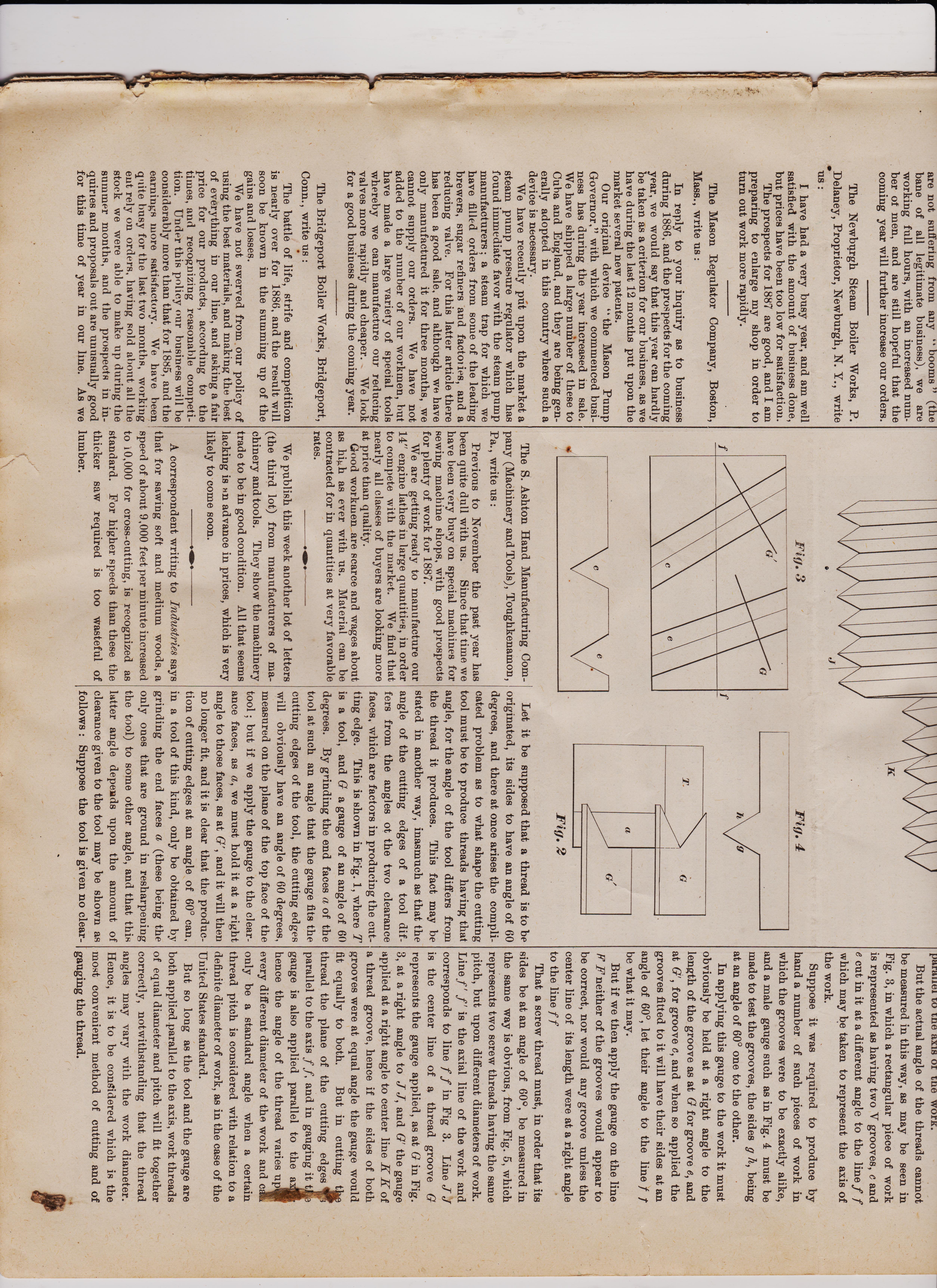
The angle of the sides, one to the other, of the United States Standard, of the common V, and of the steam and gas thread, is said to be that of 60 degrees; but it can be shown that a thread can only have a standard angle upon one diameter of bolt or work, and that for this one diameter the angle of the thread is different from that of the tool that cuts it. This in no way detracts from the value of a standard, because it is by means of the stand-ard that we are enabled to originate threads, and be sure that all those of a given pitch will fit, let the diameter of the work b, what it may, and the actual angles of tb, threads vary as they may, upon different di-ameters of work.
Fig. 2 Let it be supposed that a thread is to be originated, its sides to have an angle of 60 degrees, and there at once arises the compli-cated problem as to what shape the cutting tool must be to produce threads having that angle, for the angle of the tool differs from the thread it produces. This fact may be stated in another way, inasmuch as that the angle of the cutting edges of a tool dif-fers from the angles of the two clearance faces, which are factors in producing the cut-ting edge. This is shown in Pig. 1, where T is a tool, and G a gauge of an angle of 60 degrees. By grinding the end faces a of the tool at such an angle that the gauge fits the cutting edges of the tool, the cutting edges will obviously have an angle of 60 degrees, measured on the plane of the top face of the tool but if we apply the gauge to the clear-ance faces, as a, we must hold it at a right angle to those faces, as at 0`, and it will then no longer fit, and it is clear that the produc-tion of cutting edges at an angle of 60° can, in a tool of this kind, only be obtained by grinding the end faces a (these being the only ones that are ground in resharpening the tool) to some other angle, and that this latter angle depends upon the amount of clearance given to the tool may be shown as follows : Suppose the tool is given no clear-
parallel LO tue axis or tue WOrK. But the actual angle of the threads cannot be measured in this way, as may be seen in Fig. 3, in which a rectangular piece of work is represented as having two V grooves, e and e cut in it at a different angle to the line f f which may be taken to represent the axis of the work. Suppose it was required to produce by hand a number of such pieces of work in which the grooves were to be exactly alike, and a male gauge such as in Fig. 4 must be made to test the grooves, the sides g h, being at an angle of 60° one to the other. In applying this gauge to the work it must obviously be held at a right angle to the length of the groove as at G for groove e, and at G', for groove c, and when so applied the grooves fitted to it will have their sides at an angle of 60°, let their angle to the line I be what it may. But if we then apply the gauge on the line F neither of the grooves would appear to be correct, nor would any groove unless the center line of its length were at a right angle to the line f f That a screw thread must, in order that its sides be at an angle of 60°, be measured in the same way is obvious, from Fig. 5, which represents two screw threads having the same pitch, but upon different diameters of work. Line f ' f' is the axial line of the work and corresponds to line f f in Fig 3. Line J J is the center line of a thread groove G represents the gauge applied, as at G in Fig. 3, at a right angle to J J, and G' the gauge applied at a right angle to center line K K of a thread groove, hence if the sides of both grooves were at equal angle the gauge would fit equally to both. But in cutting t thread the plane of the cutting edges Ir; parallel to the axis f f, and in gauging it t gauge is also applied parallel to the a hence the angle of the thread varies up every different diameter of the work and c only be a standard angle when a certain thread pitch is considered with relation to a definite diameter of work, as in the case of the United States standard. But so long as the tool and the gauge are both applied ,parallel to the axis, work threads of equal diameter and pitch will fit together correctly, notwithstanding that the thread angles may vary with the work diameter. Hence, it is to be considered which is the most convenient method of cutting and of gauging the thread. _Fig. 3 Fig. 4
mace, as in Fig. 2, and the gauge may be applied parallel to the top face of the tool, and at any part of the tool depth, and will still show the same result ; or, in other words, if it fits the tool in position G, it will also do so in position (7'. But the tool must have a certain amount of clearance on its end faces a, in order to enable it to cut, and it follows that for every variation in the amount of clearance the end faces a must be ground to some angle other than that of 60 in order to produce cutting edges that shall be at an angle of 60. In the practice of the ordinary workshop t his has a minor importance, because, so long is the tool is ground so that it fits the gauge when applied in position G in the figures, the workman need not concern himself with what particular angle or amount of clearance lie has given to the tool in order to obtain correct cutting edges, all that he needs to insure being that the cutting edges are at t he correct angle, and that the amount of clearance is suitable for the diameter of the work the tool is to operate upon, and the pitch of the thread the tool is to cut. But in the manufacture of threading tools it assumes great importance, because the fit and-try process is too expensive ; hence a definite de-gree of clearance is adopted, and with it such an angle of end face as will produce cutting edges of the correct angle, when the gauge is applied parallel to the upper face of the tool. When we come to apply a thread gauge to the work we are met with new considerations arising from the angle of the thread to the axis of the work, every varying angle giving in realty a different form of thread, although all the threads may be cut by the same tool, and, furthermore, although all the threads may appear correct when tested by a gauge applied parallel to the axis of the work. But the actual angle of the threads cannot be measured in this way, as may be seen in Fig. 3, in which a rectangular piece of work is represented as having two V grooves, c and e cut in it at a different angle to the line f f which may be taken to represent the axis of the work. Suppose it was required to produce by hand a number of such pieces of work in which the grooves were to be exactly alike, and a male gauge such as in Fig. 4 must be made to test the grooves, the sides g h, being at an angle of 60° one to the other.
The E. Horton & Son Company (Manufac-turers of the Horton Lathe Chuck), Windsor Locks, Conn., write us :
Our business has been gradually improv-ing during the year just past. We are now, and have been, running to our full capacity. We are constantly adding new sizes and styles to our line of chucks as fast as there is a demand for such. Our patent car-wheel chuck is giving perfect satisfaction, and our " Horton Giant " is attracting considerable attention, and orders are beginning to come in for it The prospect for doing a good business the coming year is good, and with the end in view of doing more, we have lately added some new and improved ma-chinery to our works, and shall no doubt put in still more before the end of the year. Oneida Steam Engine and Foundry Com-pany (Lathe and Drill Chucks), Oneida, N. Y., write us: The sales of the Westcott chucks in the past year have been remarkably good, and largely in excess of any previous year. We have had all that we could do, and are now in-creasing our capacity, by adding new ma-chinery, and in using all the help we can find room for. Since the boom of 1880-'81 we have doub-- led our fac lities for manufacturing, but still find it difficult to meet the demands of our customers. There has been a marked increase of for-eign orders, and home orders have taken a decided jump, as the year closes upon us. We look forward for a busy year.
The Kensington Engine Works (Limited), Philadelphia, Pa., write us : The early part of the present year found us with a fair amount of work, and believing that the outlook was sufficiently promising, made a large addition to our works of a new boiler and blacksmith shop, thus greatly increasing our facilities. This belief of im-proved business prospects has been realized in the latter part of the year; and while we are not suffering from any " booms " (the bane of all legitimate business), we are working full hours, with an increased num-ber of men, and are still hopeful that the coming year will further increase our orders. The Newburgh Steam Boiler Works, P. Delaney, Proprietor, Newburgh, N. Y., write
us I have had a very busy year, and am well satisfied with the amount of business done, but prices have been too low for satisfaction. The prospects for 1887 are good, and I am preparing to enlarge my shop in order to turn out work more rapidly. prophesied last year, prices have been the lowest in our experience of over thirty years in our line ; and notwithstanding tubes, bars and plates have been advanced in price, we see no prospect of getting more profitable prices, because it will take a great demand to fill the facilities; possibly the crazy rush for all to be served at once. to meet the supposed coming boom, may advance prices some for a time, till the facilities are again increased to meet this rushing demand, which in our opinion is the most pernicious of all business operations, requiring, as it does, to do the year's work in six months. Another bad thing is, large concerns increasing their facil-ities to get more earnings out of the very small profit competition which present facili-ties award ; one concern dues this, and others follow, so that unless there is a great and increasing demand, all are worse off than before. It is our opinion that the best policy would be to keep prices and wages up, and re-duce the product. But such is life, and no power on earth can control the rush of men to get rich and richer in as short a time as possible ; but it is our opinion that it will take more and more time to get a competency, as the years roll on. Our predictions fi it 1884 and 1885 proved correct in the main ; but we think the prospects for 1887 more promising with us than either of the previ-ous years; and if the demand will cover in-crease of wages for skilled labor, and ad-vance in prices of stock and a little more profit, we shall be agreeably surprised.
Standard Screw Threads.
BY JOSHUA ROSE.
The angle of the sides, one to the other, of the United States Standard, of the common V, and of the steam and gas thread, is said to be that of 60 degrees; but it can be shown that a thread can only have a standard angle upon one diameter of bolt or work, and that for this one diameter the angle of the thread is different from that of the tool that cuts it. This in no way detracts from the value of a standard, because it is by means of the stand-ard that we are enabled to originate threads, and be sure that all those of a given pitch will fit, let the diameter of the work b, what it may, and the actual angles of tb, threads vary as they may, upon different di-ameters of work.
Fig. 2 Let it be supposed that a thread is to be originated, its sides to have an angle of 60 degrees, and there at once arises the compli-cated problem as to what shape the cutting tool must be to produce threads having that angle, for the angle of the tool differs from the thread it produces. This fact may be stated in another way, inasmuch as that the angle of the cutting edges of a tool dif-fers from the angles of the two clearance faces, which are factors in producing the cut-ting edge. This is shown in Pig. 1, where T is a tool, and G a gauge of an angle of 60 degrees. By grinding the end faces a of the tool at such an angle that the gauge fits the cutting edges of the tool, the cutting edges will obviously have an angle of 60 degrees, measured on the plane of the top face of the tool but if we apply the gauge to the clear-ance faces, as a, we must hold it at a right angle to those faces, as at 0`, and it will then no longer fit, and it is clear that the produc-tion of cutting edges at an angle of 60° can, in a tool of this kind, only be obtained by grinding the end faces a (these being the only ones that are ground in resharpening the tool) to some other angle, and that this latter angle depends upon the amount of clearance given to the tool may be shown as follows : Suppose the tool is given no clear-
parallel LO tue axis or tue WOrK. But the actual angle of the threads cannot be measured in this way, as may be seen in Fig. 3, in which a rectangular piece of work is represented as having two V grooves, e and e cut in it at a different angle to the line f f which may be taken to represent the axis of the work. Suppose it was required to produce by hand a number of such pieces of work in which the grooves were to be exactly alike, and a male gauge such as in Fig. 4 must be made to test the grooves, the sides g h, being at an angle of 60° one to the other. In applying this gauge to the work it must obviously be held at a right angle to the length of the groove as at G for groove e, and at G', for groove c, and when so applied the grooves fitted to it will have their sides at an angle of 60°, let their angle to the line I be what it may. But if we then apply the gauge on the line F neither of the grooves would appear to be correct, nor would any groove unless the center line of its length were at a right angle to the line f f That a screw thread must, in order that its sides be at an angle of 60°, be measured in the same way is obvious, from Fig. 5, which represents two screw threads having the same pitch, but upon different diameters of work. Line f ' f' is the axial line of the work and corresponds to line f f in Fig 3. Line J J is the center line of a thread groove G represents the gauge applied, as at G in Fig. 3, at a right angle to J J, and G' the gauge applied at a right angle to center line K K of a thread groove, hence if the sides of both grooves were at equal angle the gauge would fit equally to both. But in cutting t thread the plane of the cutting edges Ir; parallel to the axis f f, and in gauging it t gauge is also applied parallel to the a hence the angle of the thread varies up every different diameter of the work and c only be a standard angle when a certain thread pitch is considered with relation to a definite diameter of work, as in the case of the United States standard. But so long as the tool and the gauge are both applied ,parallel to the axis, work threads of equal diameter and pitch will fit together correctly, notwithstanding that the thread angles may vary with the work diameter. Hence, it is to be considered which is the most convenient method of cutting and of gauging the thread. _Fig. 3 Fig. 4
mace, as in Fig. 2, and the gauge may be applied parallel to the top face of the tool, and at any part of the tool depth, and will still show the same result ; or, in other words, if it fits the tool in position G, it will also do so in position (7'. But the tool must have a certain amount of clearance on its end faces a, in order to enable it to cut, and it follows that for every variation in the amount of clearance the end faces a must be ground to some angle other than that of 60 in order to produce cutting edges that shall be at an angle of 60. In the practice of the ordinary workshop t his has a minor importance, because, so long is the tool is ground so that it fits the gauge when applied in position G in the figures, the workman need not concern himself with what particular angle or amount of clearance lie has given to the tool in order to obtain correct cutting edges, all that he needs to insure being that the cutting edges are at t he correct angle, and that the amount of clearance is suitable for the diameter of the work the tool is to operate upon, and the pitch of the thread the tool is to cut. But in the manufacture of threading tools it assumes great importance, because the fit and-try process is too expensive ; hence a definite de-gree of clearance is adopted, and with it such an angle of end face as will produce cutting edges of the correct angle, when the gauge is applied parallel to the upper face of the tool. When we come to apply a thread gauge to the work we are met with new considerations arising from the angle of the thread to the axis of the work, every varying angle giving in realty a different form of thread, although all the threads may be cut by the same tool, and, furthermore, although all the threads may appear correct when tested by a gauge applied parallel to the axis of the work. But the actual angle of the threads cannot be measured in this way, as may be seen in Fig. 3, in which a rectangular piece of work is represented as having two V grooves, c and e cut in it at a different angle to the line f f which may be taken to represent the axis of the work. Suppose it was required to produce by hand a number of such pieces of work in which the grooves were to be exactly alike, and a male gauge such as in Fig. 4 must be made to test the grooves, the sides g h, being at an angle of 60° one to the other.
******************************************************************************
are not suffering from any " booms " (the bane of all legitimate business), we are working full hours, with an increased num-ber of men, and are still hopeful that the coming year will further increase our orders. The Newburgh Steam Boiler Works, P. Delaney, Proprietor, Newburgh, N. Y., write us :
I have had a very busy year, and am well satisfied with the amount of business done, but prices have been too low for satisfaction. The prospects for 1887 are good, and I am preparing to enlarge my shop in order to turn out work more rapidly. The Mason Regulator Company, Boston, Mass., write us : In reply to your inquiry as to business during 1886, and the prospects for the coming year, we would say that this year can hardly be taken as a criterion for our business, as we have during the last 12 months put upon the market several new patents. Our original device " the Mason Pump Governor," with which we commenced busi-ness has during the year increased in sale. We have shipped a large number of these to Cuba and England, and they are being gen-erally adopted in this country where such a device is necessary. We have recently put upon the market a steam pump pressure regulator which has found immediate favor with the steam pump manufacturers a steam trap for which we have filled orders from some of the leading brewers, sugar refiners and factories, and a reducing valve. For this latter article there has been a good sale, and although we have only manufactured it for three months, we cannot supply our orders. We have not added to the number of our workmen, but have made a large variety of special tools whereby we can manufacture our reducing valves more rapidly and cheaper. We look for a good business during the coming year. The Bridgeport Boiler Works, Bridgeport, Conn., write us : The battle of life, strife and competition is nearly over for 1886, and the result will soon be known in the summing up of the gains and losses. We have not swerved from our policy of using the best materials, and making the best of everything in our line, and asking a fair price for our products, according to the times, and recognizing reasonable competi-tion. Under this policy our business wi 11 he considerably more than that for 1885, and the earnings more satisfactory. We have been quite busy for the last two months, working eut rely on orders, having sold about all the stock we were able to make up during the summer months, and the prospects in in-quiries and proposals out are unusually good for this time of year in our line. As we e
The S. Ashton Hand Manufacturing Com-pany (Machinery and Tools), Toughkenamon, Pa., write us :
Previous to November the past year has been quite dull with us. Since that time we have been very busy on special machines for sewing machine shops, with good prospects for plenty of work for 1887. We are getting ready to manufacture our 14" engine lathes in large quantities, in order to compete with the market. We find that nearly all classes of buyers are looking more at price than quality. Good workmen are scarce and wages about as high as ever with us. Material can be contracted for in quantities at very favorable rates. •111111.• - We publish this week another lot of letters (the third lot) from manufacturers of ma-chinery and tools. They show the machinery trade to be in good condition. All that seems lacking is advance in prices, which is very likely to come soon. .11111.• A correspondent writing to Industries says that for sawing soft and medium woods, a speed of about 9,000 feet per minute increased to 10,000 for cross-cutting, is recognized as standard. For higher speeds than these the thicker saw required is too wasteful of lumber. a
pg 4 AMERICAN MACHINIST JANUARY 22, 1887
Standard Screw Threads.
BY JOSHUA ROSE.
The angle of the sides, one to the other, of the United States Standard, of the common V, and of the steam and gas thread, is said to be that of 60 degrees; but it can be shown that a thread can only have a standard angle upon one diameter of bolt or work, and that for this one diameter the angle of the thread is different from that of the tool that cuts it. This in no way detracts from the value of a standard, because it is by means of the stand-ard that we are enabled to originate threads, and be sure that all those of a given pitch will fit, let the diameter of the work b, what it may, and the actual angles of tb, threads vary as they may, upon different di-ameters of work.
Fig. 2 Let it be supposed that a thread is to be originated, its sides to have an angle of 60 degrees, and there at once arises the compli-cated problem as to what shape the cutting tool must be to produce threads having that angle, for the angle of the tool differs from the thread it produces. This fact may be stated in another way, inasmuch as that the angle of the cutting edges of a tool dif-fers from the angles of the two clearance faces, which are factors in producing the cut-ting edge. This is shown in Pig. 1, where T is a tool, and G a gauge of an angle of 60 degrees. By grinding the end faces a of the tool at such an angle that the gauge fits the cutting edges of the tool, the cutting edges will obviously have an angle of 60 degrees, measured on the plane of the top face of the tool but if we apply the gauge to the clear-ance faces, as a, we must hold it at a right angle to those faces, as at 0`, and it will then no longer fit, and it is clear that the produc-tion of cutting edges at an angle of 60° can, in a tool of this kind, only be obtained by grinding the end faces a (these being the only ones that are ground in resharpening the tool) to some other angle, and that this latter angle depends upon the amount of clearance given to the tool may be shown as follows : Suppose the tool is given no clear-
parallel LO tue axis or tue WOrK. But the actual angle of the threads cannot be measured in this way, as may be seen in Fig. 3, in which a rectangular piece of work is represented as having two V grooves, e and e cut in it at a different angle to the line f f which may be taken to represent the axis of the work. Suppose it was required to produce by hand a number of such pieces of work in which the grooves were to be exactly alike, and a male gauge such as in Fig. 4 must be made to test the grooves, the sides g h, being at an angle of 60° one to the other. In applying this gauge to the work it must obviously be held at a right angle to the length of the groove as at G for groove e, and at G', for groove c, and when so applied the grooves fitted to it will have their sides at an angle of 60°, let their angle to the line I be what it may. But if we then apply the gauge on the line F neither of the grooves would appear to be correct, nor would any groove unless the center line of its length were at a right angle to the line f f That a screw thread must, in order that its sides be at an angle of 60°, be measured in the same way is obvious, from Fig. 5, which represents two screw threads having the same pitch, but upon different diameters of work. Line f ' f' is the axial line of the work and corresponds to line f f in Fig 3. Line J J is the center line of a thread groove G represents the gauge applied, as at G in Fig. 3, at a right angle to J J, and G' the gauge applied at a right angle to center line K K of a thread groove, hence if the sides of both grooves were at equal angle the gauge would fit equally to both. But in cutting t thread the plane of the cutting edges Ir; parallel to the axis f f, and in gauging it t gauge is also applied parallel to the a hence the angle of the thread varies up every different diameter of the work and c only be a standard angle when a certain thread pitch is considered with relation to a definite diameter of work, as in the case of the United States standard. But so long as the tool and the gauge are both applied ,parallel to the axis, work threads of equal diameter and pitch will fit together correctly, notwithstanding that the thread angles may vary with the work diameter. Hence, it is to be considered which is the most convenient method of cutting and of gauging the thread. _Fig. 3 Fig. 4
mace, as in Fig. 2, and the gauge may be applied parallel to the top face of the tool, and at any part of the tool depth, and will still show the same result ; or, in other words, if it fits the tool in position G, it will also do so in position (7'. But the tool must have a certain amount of clearance on its end faces a, in order to enable it to cut, and it follows that for every variation in the amount of clearance the end faces a must be ground to some angle other than that of 60 in order to produce cutting edges that shall be at an angle of 60. In the practice of the ordinary workshop t his has a minor importance, because, so long is the tool is ground so that it fits the gauge when applied in position G in the figures, the workman need not concern himself with what particular angle or amount of clearance lie has given to the tool in order to obtain correct cutting edges, all that he needs to insure being that the cutting edges are at t he correct angle, and that the amount of clearance is suitable for the diameter of the work the tool is to operate upon, and the pitch of the thread the tool is to cut. But in the manufacture of threading tools it assumes great importance, because the fit and-try process is too expensive ; hence a definite de-gree of clearance is adopted, and with it such an angle of end face as will produce cutting edges of the correct angle, when the gauge is applied parallel to the upper face of the tool. When we come to apply a thread gauge to the work we are met with new considerations arising from the angle of the thread to the axis of the work, every varying angle giving in realty a different form of thread, although all the threads may be cut by the same tool, and, furthermore, although all the threads may appear correct when tested by a gauge applied parallel to the axis of the work. But the actual angle of the threads cannot be measured in this way, as may be seen in Fig. 3, in which a rectangular piece of work is represented as having two V grooves, c and e cut in it at a different angle to the line f f which may be taken to represent the axis of the work. Suppose it was required to produce by hand a number of such pieces of work in which the grooves were to be exactly alike, and a male gauge such as in Fig. 4 must be made to test the grooves, the sides g h, being at an angle of 60° one to the other.
The E. Horton & Son Company (Manufac-turers of the Horton Lathe Chuck), Windsor Locks, Conn., write us :
Our business has been gradually improv-ing during the year just past. We are now, and have been, running to our full capacity. We are constantly adding new sizes and styles to our line of chucks as fast as there is a demand for such. Our patent car-wheel chuck is giving perfect satisfaction, and our " Horton Giant " is attracting considerable attention, and orders are beginning to come in for it The prospect for doing a good business the coming year is good, and with the end in view of doing more, we have lately added some new and improved ma-chinery to our works, and shall no doubt put in still more before the end of the year. Oneida Steam Engine and Foundry Com-pany (Lathe and Drill Chucks), Oneida, N. Y., write us: The sales of the Westcott chucks in the past year have been remarkably good, and largely in excess of any previous year. We have had all that we could do, and are now in-creasing our capacity, by adding new ma-chinery, and in using all the help we can find room for. Since the boom of 1880-'81 we have doub-- led our fac lities for manufacturing, but still find it difficult to meet the demands of our customers. There has been a marked increase of for-eign orders, and home orders have taken a decided jump, as the year closes upon us. We look forward for a busy year.
The Kensington Engine Works (Limited), Philadelphia, Pa., write us : The early part of the present year found us with a fair amount of work, and believing that the outlook was sufficiently promising, made a large addition to our works of a new boiler and blacksmith shop, thus greatly increasing our facilities. This belief of im-proved business prospects has been realized in the latter part of the year; and while we are not suffering from any " booms " (the bane of all legitimate business), we are working full hours, with an increased num-ber of men, and are still hopeful that the coming year will further increase our orders. The Newburgh Steam Boiler Works, P. Delaney, Proprietor, Newburgh, N. Y., write
us I have had a very busy year, and am well satisfied with the amount of business done, but prices have been too low for satisfaction. The prospects for 1887 are good, and I am preparing to enlarge my shop in order to turn out work more rapidly. prophesied last year, prices have been the lowest in our experience of over thirty years in our line ; and notwithstanding tubes, bars and plates have been advanced in price, we see no prospect of getting more profitable prices, because it will take a great demand to fill the facilities; possibly the crazy rush for all to be served at once. to meet the supposed coming boom, may advance prices some for a time, till the facilities are again increased to meet this rushing demand, which in our opinion is the most pernicious of all business operations, requiring, as it does, to do the year's work in six months. Another bad thing is, large concerns increasing their facil-ities to get more earnings out of the very small profit competition which present facili-ties award ; one concern dues this, and others follow, so that unless there is a great and increasing demand, all are worse off than before. It is our opinion that the best policy would be to keep prices and wages up, and re-duce the product. But such is life, and no power on earth can control the rush of men to get rich and richer in as short a time as possible ; but it is our opinion that it will take more and more time to get a competency, as the years roll on. Our predictions fi it 1884 and 1885 proved correct in the main ; but we think the prospects for 1887 more promising with us than either of the previ-ous years; and if the demand will cover in-crease of wages for skilled labor, and ad-vance in prices of stock and a little more profit, we shall be agreeably surprised.
Standard Screw Threads.
BY JOSHUA ROSE.
The angle of the sides, one to the other, of the United States Standard, of the common V, and of the steam and gas thread, is said to be that of 60 degrees; but it can be shown that a thread can only have a standard angle upon one diameter of bolt or work, and that for this one diameter the angle of the thread is different from that of the tool that cuts it. This in no way detracts from the value of a standard, because it is by means of the stand-ard that we are enabled to originate threads, and be sure that all those of a given pitch will fit, let the diameter of the work b, what it may, and the actual angles of tb, threads vary as they may, upon different di-ameters of work.
Fig. 2 Let it be supposed that a thread is to be originated, its sides to have an angle of 60 degrees, and there at once arises the compli-cated problem as to what shape the cutting tool must be to produce threads having that angle, for the angle of the tool differs from the thread it produces. This fact may be stated in another way, inasmuch as that the angle of the cutting edges of a tool dif-fers from the angles of the two clearance faces, which are factors in producing the cut-ting edge. This is shown in Pig. 1, where T is a tool, and G a gauge of an angle of 60 degrees. By grinding the end faces a of the tool at such an angle that the gauge fits the cutting edges of the tool, the cutting edges will obviously have an angle of 60 degrees, measured on the plane of the top face of the tool but if we apply the gauge to the clear-ance faces, as a, we must hold it at a right angle to those faces, as at 0`, and it will then no longer fit, and it is clear that the produc-tion of cutting edges at an angle of 60° can, in a tool of this kind, only be obtained by grinding the end faces a (these being the only ones that are ground in resharpening the tool) to some other angle, and that this latter angle depends upon the amount of clearance given to the tool may be shown as follows : Suppose the tool is given no clear-
parallel LO tue axis or tue WOrK. But the actual angle of the threads cannot be measured in this way, as may be seen in Fig. 3, in which a rectangular piece of work is represented as having two V grooves, e and e cut in it at a different angle to the line f f which may be taken to represent the axis of the work. Suppose it was required to produce by hand a number of such pieces of work in which the grooves were to be exactly alike, and a male gauge such as in Fig. 4 must be made to test the grooves, the sides g h, being at an angle of 60° one to the other. In applying this gauge to the work it must obviously be held at a right angle to the length of the groove as at G for groove e, and at G', for groove c, and when so applied the grooves fitted to it will have their sides at an angle of 60°, let their angle to the line I be what it may. But if we then apply the gauge on the line F neither of the grooves would appear to be correct, nor would any groove unless the center line of its length were at a right angle to the line f f That a screw thread must, in order that its sides be at an angle of 60°, be measured in the same way is obvious, from Fig. 5, which represents two screw threads having the same pitch, but upon different diameters of work. Line f ' f' is the axial line of the work and corresponds to line f f in Fig 3. Line J J is the center line of a thread groove G represents the gauge applied, as at G in Fig. 3, at a right angle to J J, and G' the gauge applied at a right angle to center line K K of a thread groove, hence if the sides of both grooves were at equal angle the gauge would fit equally to both. But in cutting t thread the plane of the cutting edges Ir; parallel to the axis f f, and in gauging it t gauge is also applied parallel to the a hence the angle of the thread varies up every different diameter of the work and c only be a standard angle when a certain thread pitch is considered with relation to a definite diameter of work, as in the case of the United States standard. But so long as the tool and the gauge are both applied ,parallel to the axis, work threads of equal diameter and pitch will fit together correctly, notwithstanding that the thread angles may vary with the work diameter. Hence, it is to be considered which is the most convenient method of cutting and of gauging the thread. _Fig. 3 Fig. 4
mace, as in Fig. 2, and the gauge may be applied parallel to the top face of the tool, and at any part of the tool depth, and will still show the same result ; or, in other words, if it fits the tool in position G, it will also do so in position (7'. But the tool must have a certain amount of clearance on its end faces a, in order to enable it to cut, and it follows that for every variation in the amount of clearance the end faces a must be ground to some angle other than that of 60 in order to produce cutting edges that shall be at an angle of 60. In the practice of the ordinary workshop t his has a minor importance, because, so long is the tool is ground so that it fits the gauge when applied in position G in the figures, the workman need not concern himself with what particular angle or amount of clearance lie has given to the tool in order to obtain correct cutting edges, all that he needs to insure being that the cutting edges are at t he correct angle, and that the amount of clearance is suitable for the diameter of the work the tool is to operate upon, and the pitch of the thread the tool is to cut. But in the manufacture of threading tools it assumes great importance, because the fit and-try process is too expensive ; hence a definite de-gree of clearance is adopted, and with it such an angle of end face as will produce cutting edges of the correct angle, when the gauge is applied parallel to the upper face of the tool. When we come to apply a thread gauge to the work we are met with new considerations arising from the angle of the thread to the axis of the work, every varying angle giving in realty a different form of thread, although all the threads may be cut by the same tool, and, furthermore, although all the threads may appear correct when tested by a gauge applied parallel to the axis of the work. But the actual angle of the threads cannot be measured in this way, as may be seen in Fig. 3, in which a rectangular piece of work is represented as having two V grooves, c and e cut in it at a different angle to the line f f which may be taken to represent the axis of the work. Suppose it was required to produce by hand a number of such pieces of work in which the grooves were to be exactly alike, and a male gauge such as in Fig. 4 must be made to test the grooves, the sides g h, being at an angle of 60° one to the other.
******************************************************************************
are not suffering from any " booms " (the bane of all legitimate business), we are working full hours, with an increased num-ber of men, and are still hopeful that the coming year will further increase our orders. The Newburgh Steam Boiler Works, P. Delaney, Proprietor, Newburgh, N. Y., write us :
I have had a very busy year, and am well satisfied with the amount of business done, but prices have been too low for satisfaction. The prospects for 1887 are good, and I am preparing to enlarge my shop in order to turn out work more rapidly. The Mason Regulator Company, Boston, Mass., write us : In reply to your inquiry as to business during 1886, and the prospects for the coming year, we would say that this year can hardly be taken as a criterion for our business, as we have during the last 12 months put upon the market several new patents. Our original device " the Mason Pump Governor," with which we commenced busi-ness has during the year increased in sale. We have shipped a large number of these to Cuba and England, and they are being gen-erally adopted in this country where such a device is necessary. We have recently put upon the market a steam pump pressure regulator which has found immediate favor with the steam pump manufacturers a steam trap for which we have filled orders from some of the leading brewers, sugar refiners and factories, and a reducing valve. For this latter article there has been a good sale, and although we have only manufactured it for three months, we cannot supply our orders. We have not added to the number of our workmen, but have made a large variety of special tools whereby we can manufacture our reducing valves more rapidly and cheaper. We look for a good business during the coming year. The Bridgeport Boiler Works, Bridgeport, Conn., write us : The battle of life, strife and competition is nearly over for 1886, and the result will soon be known in the summing up of the gains and losses. We have not swerved from our policy of using the best materials, and making the best of everything in our line, and asking a fair price for our products, according to the times, and recognizing reasonable competi-tion. Under this policy our business wi 11 he considerably more than that for 1885, and the earnings more satisfactory. We have been quite busy for the last two months, working eut rely on orders, having sold about all the stock we were able to make up during the summer months, and the prospects in in-quiries and proposals out are unusually good for this time of year in our line. As we e
The S. Ashton Hand Manufacturing Com-pany (Machinery and Tools), Toughkenamon, Pa., write us :
Previous to November the past year has been quite dull with us. Since that time we have been very busy on special machines for sewing machine shops, with good prospects for plenty of work for 1887. We are getting ready to manufacture our 14" engine lathes in large quantities, in order to compete with the market. We find that nearly all classes of buyers are looking more at price than quality. Good workmen are scarce and wages about as high as ever with us. Material can be contracted for in quantities at very favorable rates. •111111.• - We publish this week another lot of letters (the third lot) from manufacturers of ma-chinery and tools. They show the machinery trade to be in good condition. All that seems lacking is advance in prices, which is very likely to come soon. .11111.• A correspondent writing to Industries says that for sawing soft and medium woods, a speed of about 9,000 feet per minute increased to 10,000 for cross-cutting, is recognized as standard. For higher speeds than these the thicker saw required is too wasteful of lumber. a
AMERICAN-MACHINIST-1887-page 3 January-22-Vol-10-No 4

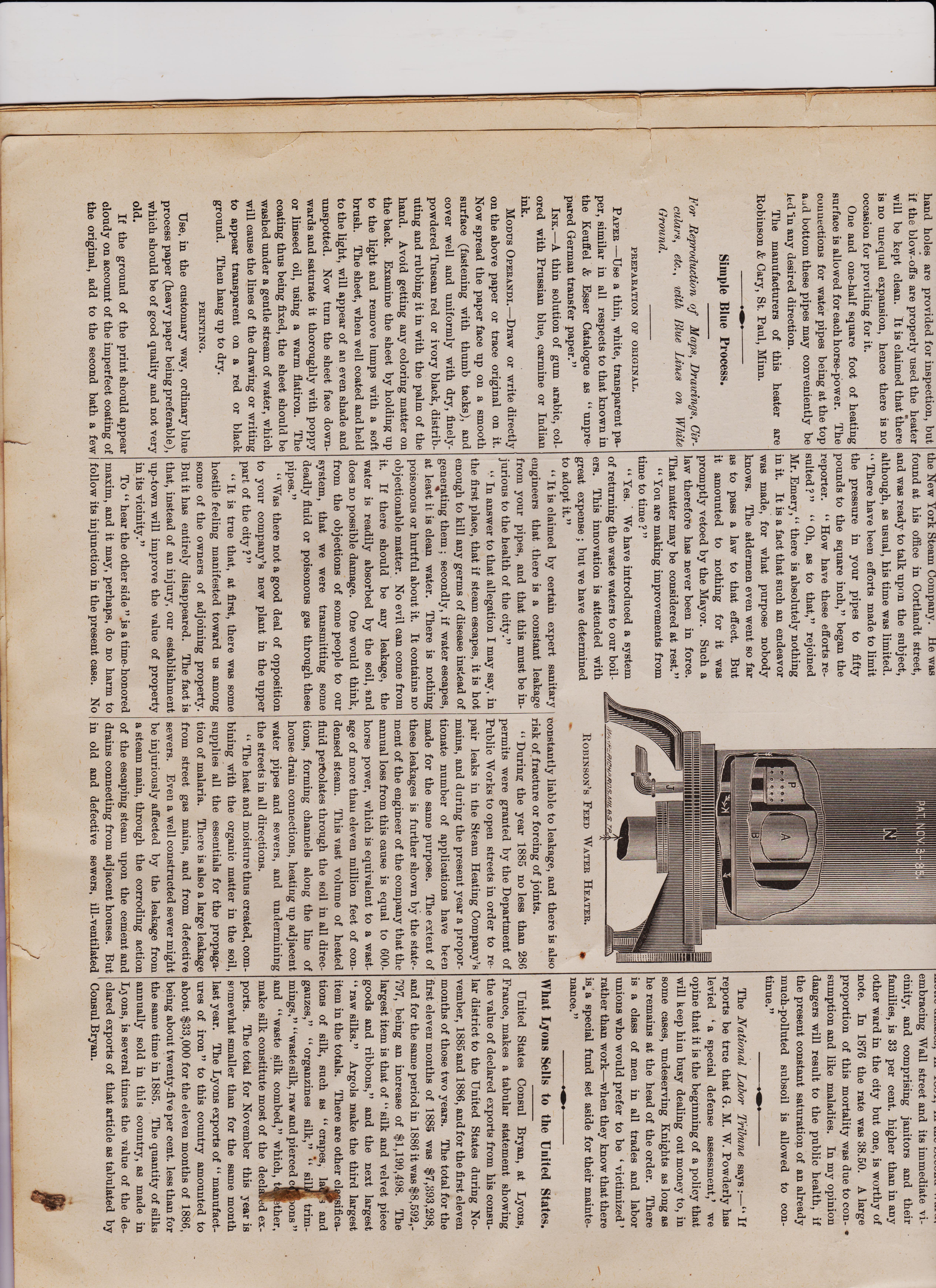
AMERICAN MACHINIST January-22-1887 page 4
br>AMERICAN MACHINIST January 15 1887 pg 4
<
DECEMBER 31, 1887 pg 4
AMERICAN MACHINIST
Robinson's Feed Water Heater.
The heater proper consists of a vertical shell, with a series of tubes, the central one being larger than the others. This shell is surrounded by another which encloses a small space, except at the top and bottom, where there are comparatively large chambers en-closed. The exhaust from the engine enters at the bottom through pipe A, and passes up to near the top of heater, and into chamber E. From there it passes down through the tubes and through the space between the shells, to lower chamber K, and into pipe I, whence it may pass .to the atmosphere, or to the con-denser, or may be conducted away and used for heating purposes. The water is forced in through pipe /1, and passes out to the boiler through pipe 0, thus becoming heated before coming in contact with the shell or tubes of the heater. A cir-culation of water is maintained by its rising upward in contact with tube (I, and flowing downward in contact with the surface of chamber P. Impurities are carried to a com-paratively quiet space above and below P, and may be blown off through pipes 0 and J. The heater contains water enough to supply the boiler for twenty minutes, which is suffi. cient to allow for heating, and to permit im-purities to settle, or to rise to the top. The steam from pipe A escaping in a verti-cal direction into chamber E, and leaving it in the reverse direction, maintains the cham-ber full, equally supplying all the tubes and space with heat. The currents of steam are downwards, thus relieving the heater of the water of condensation. The head of the jacket is arranged so that it can be removed, and the heater removed from the jacket, in case repairs are needed ; hand holes are provided for inspection, but if the blow-offs are properly used the heater will be kept clean. It is claimed that there is no unequal expansion, hence there is no occasion for providing for it. One and one-half square foot of heating surface is allowed for each horse-power. The connections for water pipes being at the top a. bottom these pipes may conveniently be led in any desired direction. The manufacturers of this heater are Robinson & Cary, St. Paul, Minn.
Carrying Steam Through Streets at High Pressure.
The New York Steam Company has been extending its business during the last three or four years until it has seven or eight miles of main pipes running through the streets, supplying steam, heat and power to hundreds of customers. It has met considerable oppo-sition at times, and lately the Board of Aldermen passed a bill requiring the pressure in its mains to be reduced to 50 pounds. The Mayor vetoed the bill. It has been urged that the city is in danger of malarial poisoning from leak-ages of the main steam pipes. It is said that the pipes are leaky in many places, and that the miasmic emanations thereby occasioned are deleterious to the public health, and cause diseases. In order to learn the pros and cons of this public question, a reporter of the AMERICAN MACHINIST called upon two gentlemen, who, from their positions, have taken sides prominently for and against the company. The first was Charles E. Emery, Chief Engineer of the New York Steam Company. He was found at his office in Cortlandt street, and was ready to talk upon the subject, although, as usual, his time was limited. " There have been efforts made to limit the pressure in your pipes to fifty pounds to the square inch," began the reporter. " How have these efforts re-sulted ?" " Oh, as to that," rejoined Mr. Emery," there is absolutely nothing in it. It is a fact that such an endeavor was made, for what purpose nobody knows. The aldermen even went so far as to pass a law to that effect. But one needs an introduction to C. F. Wingate, the Sanitary Engineer. To him the reporter applied for his views of the question at issue. " Well," responded Mr. Wingate, " my opinion to-day is what it was when I sent my report to an investigating committee. I have seen no reason to change it. As I stated then, the facts in the case are as follows: " The company maintains some 71 miles of street mains, covering the district from Duane Street to the Battery, and are making further extensions. These mains are of an average size of 10 inches, and are laid at an average depth of six feet. They are made of lap-welded wrought iron, but the material, it is declared, is not always of the best, as, owing to the intense heat, to which the material is subjected in the process of making, it be-comes crystalline,or what is technically known as cold short,' and is then, in the opinion of experts, not one-third as durable as ordinary boiler iron. Under pressure of 90 pounds to which these pipes are now subjected they are
JANUARY 22, 1887
and ill-flushed, the effect of such leakage must be exceedingly harmful. Decomposition will be assisted, and the foul gases thereby created will be forced through traps, and into dwellings. " Where drains are laid in made land the miasma created in the soil will be drawn di-rectly into houses, as has frequently happened with escaping gas from leaking street mains. So many sub-cellars down town are lower than the sewer line, that any ground soakage would tend toward them. I have noticed a strong odor in such basement vaults. Hun-dreds of warehouses and stores have vaults extending under the sidewalk, and the Steam Heating Company have had to carry their pipes directly through these vaults, where a break or a leak might do great damage. " It is claimed that the mains do not heat the ground around and above them, because the snow in winter does not melt any sooner along the street above the steam pipes than elsewhere. This may be true, yet it is nevertheless undeniable that large water mains are warmed by contact with the steana,mains,!and that ,leaks may be detected by the more rapid drying of the ground above them in rainy or snowy weather. In the course of time, as the strain becomes greater, these leaks will doubtless multiply, and their effects become more extended. It is not surprising to learn that already malarial sick-ness is reported On the increase in the region along the line of the company's mains, and its further extension is to be expected. " From my personal experience I know that many oases of serious sickness are contracted in office buildings where business men and their employes are too absorbed in their daily routine to observe this foul and poison-ous atmosphere, which is their lung food. The fact that the annual death rate from zy-motic disases, in 1884, in the Second Ward, embracing Wall street and its immediate vi-cinity, and comprising janitors and their families, is 33 per cent. higher than in any other ward in the city but one, is worthy of note. In 1876 the rate was 38.50. A large proportion of this mortality was due to con-sumption and like maladies. In my opinion dangers will result to the public health, if the present constant saturation of an already much-polluted subsoil is allowed to con-tinue." The National Labor Tribune says :—" If
***********************************************************
hand holes are provided for inspection, but if the blow-offs are properly used the heater will be kept clean. It is claimed that there isno unequal expansion, hencen there is no occasion for providing for it. One and one-half square foot of heating surface is allowed for each horse-power. The connections for water pipes being at the top avid bottom these pipes may conveniently be led qu any desired direction. The manufacturers of this heater are Robinson & Cary, St. Paul, Minn.
Simple Blue Process.
For Reproduction, of Maps, Drawings, Cir-culars, etc. , with Blue Lines on White Ground. PREPARATION OF ORIGINAL. PAPER —Use a thin, white, transparent pa-per, similar in all respects to that known in the Keuffel & Esser Catalogue as " unpre-pared German transfer paper." INK. —A thin solution of gum arable, col-ored with Prussian blue, carmine or Indian ink. MODUS OPERANDI.-Draw or write directly on the above paper or trace original on it. Now spread the paper face up on a smooth surface (fastening with thumb tacks), and cover well and uniformly with dry, finely-powdered Tuscan red or ivory black, distrib-uting and rubbing it in with the palm of the hand. Avoid getting any coloring matter on the back. Examine the sheet by holding up to the light and remove lumps with a soft brush. The sheet, when well coated and held to the light, will appear of an even shade and unspotted. Now turn the sheet face down-wards and saturate it thoroughly with poppy or linseed oil, using a warm flatiron. The coating thus being fixed, the sheet should be washed under a gentle stream of water, which will cause the lines of the drawing or writing to appear transparent on a red or black ground. Then hang up to dry.
PRINTING.
Use, in the customary way, ordinary blue process paper (heavy paper being preferable), which should be of good quality and not very old. If the ground of the print should appear cloudy on account of the imperfect coating of the original, add to the second bath a few the New York Steam Company. lie was found at his office in Cortlandt street, and was ready to talk upon the subject, although, _ as usual, his time was limited. -0 - drops of a saturated solution of chloride of lime, and watch the bleaching. When the ground is perfectly white and clear, wash again in clear water. HENRY BOSSE, Draftsman. U. S. Engineer Office, Rock Island, Ill. The manuscript from which these direc-tions have been printed, is, we believe, a re-production of the original and obtained by this process. If so, the result is excellent, and since the process is comparatively simple, our readers may find it to be advantageous to adopt the same.
ROI3INSON'S FEED WATER HEATER.
constantly liable to leakage, and there is also risk of fracture or forcing of joints. " During the year 1885 no less than 286 permits were granted by the Department of Public Works to open streets in order to re pair leaks in the Steam Heating Company's mains, and during the present year a propor tionate number of applications have been made for the same purpose. The extent of these leakages is further shown by the state-ment of the engineer of the company that the annual loss from this cause is equal to 60C horse power, which is equivalent to a wast age of more than eleven million feet of con-densed steam. This vast volume of heated fluid pertolates through the soil in all dire( tions, forming channels along the line of house drain connections, heating up adjacent water pipes and sewers, and undermining " There have been efforts made to limit the pressure in your pipes to fifty pounds to the square inch," began the reporter. " How have these efforts re-sulted ? " " Oh, as to that," rejoined Mr. Emery," there is absolutely nothing in it. It is a fact that such an endeavor was made, for what purpose nobody knows. The aldermen even went so far as to pass a law to that effect. But it amounted to nothing for it was promptly vetoed by the Mayor. Such a law therefore has never been in force. That matter may be considered at rest." " You are making improvements from time to time ? " " Yes. We have introduced a system of returning the waste waters to our boil-ers. This innovation is attended with great expense ; but we have determined to adopt it." " It is claimed by certain expert sanitary engineers that there is a constant leakage from your pipes, and that this must be in-jurious to the health of the city." " In answer to that allegation I may say, in the first place, that if steam escapes, it is hot enough to kill any germs of disease instead of geneTting them secondly, if water escapes, at least it is clean water. There is nothing poisonous or hurtful about it. It contains no objectionable matter. No evil can come from it. If there should be any leakage, the water is readily absorbed by the soil, and does no possible damage. One would think, from the objections of some people to our system, that we were transmitting some deadly fluid or poisonous gas through these pipes." " Was there not a good deal of opposition to your company's new plant in the upper I part of the city?"
" It is true that, at first, there was some hostile feeling manifested toward us among some of the owners of adjoining property. But it has entirely disappeared. The fact is that, instead of an injury, our establishment up-town will improve the value of property in its vicinity." To " hear the other side ".is a time-honored maxim, and it may, perhaps, do no harm to follow its injunction in the present case. No
the streets in all directions. " The heat and moisture thus created. con bining with the organic matter in the soil, supplies all the essentials for the propaga-tion of malaria. There is also a large leakage from street gas mains, and from defective sewers. Even a well-constructed sewer might be injuriously affected by the leakage from a steam main, through the corroding action of the escaping steam upon the cement and drains connecting from adjacent houses. But in old and defective sewers, ill-ventilated embracing Wall street and its immediate vi-cinity, and comprising janitors and their families, is 33 per cent. higher than in any other ward in the city but one, is worthy of note. In 1876 the rate was 38.50. A large proportion of this mortality was due to con-sumption and like maladies. In my opinion dangers will result to the public health, if the present constant saturation of an already much-polluted subsoil is allowed to con-tinue." The National Labor Tribune says : If reports be true that G. M. W. Powderly has levied a special defense assessment,' we opine that it is the beginning of a policy that will keep him busy dealing out money to, in some cases, undeserving Knights as long as he remains at the head of the order. There is a class of men in all trades and labor unions who would prefer to be victimized' rather than work—when they know that there is.; a special fund set aside for their mainte-nance."
What Lyons Sells to the United States.
United States Consul Bryan, at Lyons, France, makes a tabular statement showing the value of declared exports from his consu-lar district to the United States during No-vember, 1885 and 1886, and for the first eleven months of those two years. The total for the first eleven months of 1885 was $7,393,298, and for the same period in 1886 it was $8,592,-797, being an increase of $1,199,498. The largest item is that of " silk and velvet piece goods and ribbons," and the next largest " raw silks." Argols make the third largest item in the totals. There are other cl sifica-tions of silk, such as " crapes, la and gauzes," " organzines silk," " sil trim-mings," "waste silk, raw and pierced c Ions " and " waste silk combed," which, t ether, make silk constitute most of the decl A ex-ports. The total for November this year is somewhat smaller than for the same month last year. The Lyons exports of " manufact-ures of iron " to this country amounted to about $33,000 for the eleven months of 1886, being about twenty-five per cent. less than for the same time in 1885. The quantity of silks annually sold in this country, as made in L3 ons, is several times the value of the de-clared exports of that article as tabulated by Consul Bryan.
AMERICAN-MACHINIST-1887-page 5 January-22-Vol-10-No 4