*********************************************
top top sky pic top size
top top sky pic top size

Antiquemachinery.com
AMERICAN MACHINIST Dec 31 1887 white
The New York Giants defeated the Brooklyn Bridegrooms (later known as the Dodgers). in the 1889 World Series, 6 games to 3.
AMERICAN MACHINIST Dec 31 1887 white
The New York Giants defeated the Brooklyn Bridegrooms (later known as the Dodgers). in the 1889 World Series, 6 games to 3.
top
top
sky
pic top
size
top
sky
pic top
size

the tet is here text
pic 1
pic 1
OCTOBER 3, 1889 Surface Grinding Machine or Grinding Planer.
A JOURNAL FOR MACHINISTS, ENGINEERS, FOUNDERS, BOILER MAKERS, PATTERN MAKERS AND BLACKSMITHS, VOL. 10, No. ,)3. WEEKLY. NEW YORK, DECEMBER 31, 1887. {82.50 per Annum. SINGLE COPIES, a CENTS, COPYRIGHT 1887, BY AMERICAN MACHINIST PUBLISHING COMPANY, For Sale Everywhere by Newsdealers.
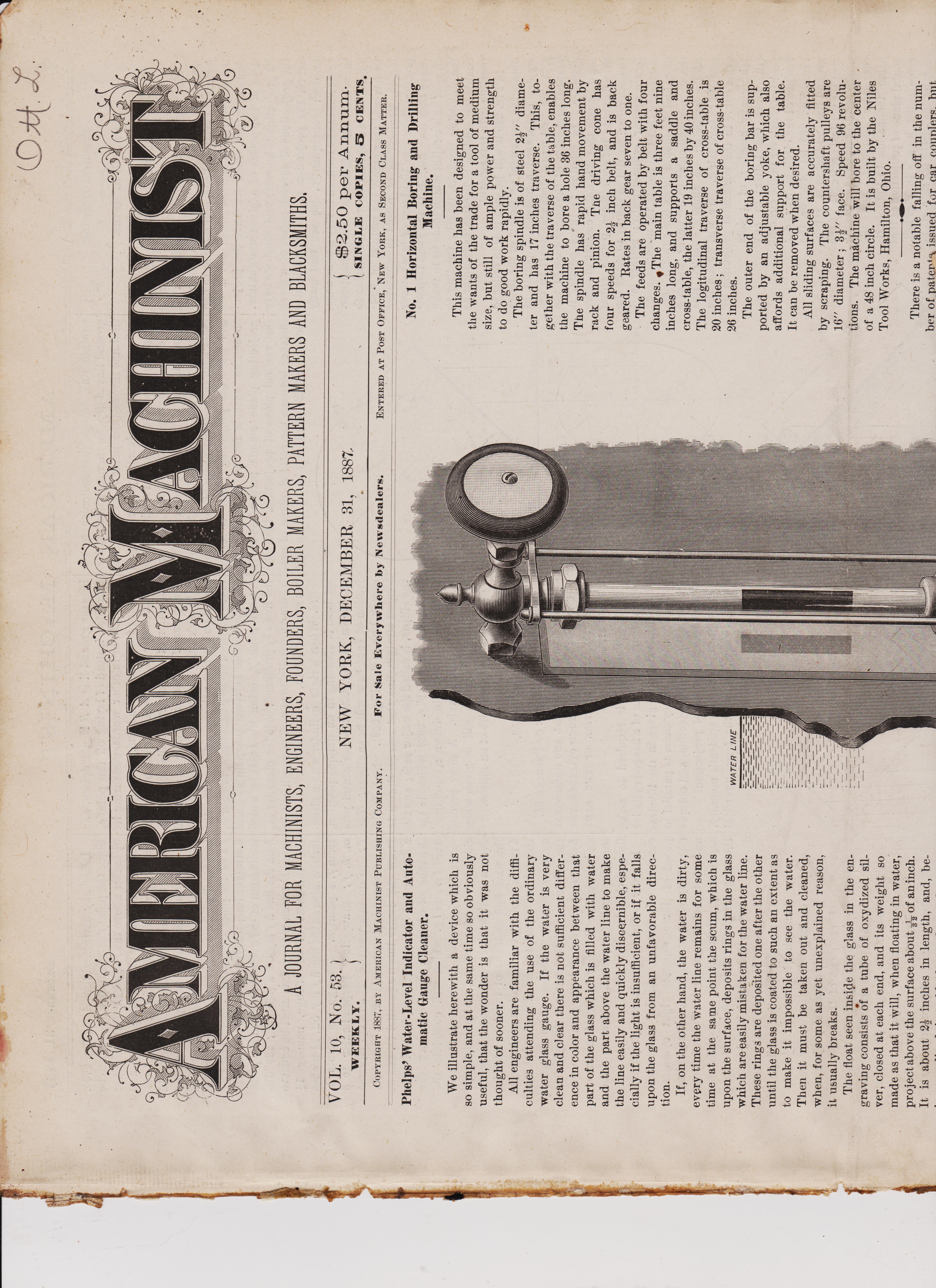
Phelps' Water-Level Indicator and Auto-matic Gauge Cleaner.
We illustrate herewith a device which is so simple, and at the same time so obviously useful, that the wonder is that it was not thought of sooner. All engineers are familiar with the difficulties attending the use of the ordinary water glass gauge. If the water is very clean and clear there is not sufficient difference in color and appearance between that part of the glass which is filled with water and the part above the water line to make the line easily and quickly discernible, especially if the light is insufficient, or if it falls upon the glass from an unfavorable direction. If, on the other hand, the water is dirty, every time the water line remains for some time at the same point the scum, which is upon the surface, deposits rings in the glass which are easily mistaken for the water line. These rings are deposited one after the other until the glass is coated to such an extent as to make it impossible to see the water. Then it must be taken out and cleaned, when, for some as yet unexplained reason, it usually breaks. The float seen inside the glass in the engraving consists of a tube of oxydized sil-ver, closed at each end, and its weight so made as that it will, when floating in water, project above the surface about of aninch. It is about 22 inches in length, and, be-
No. 1 Horizontal Boring and Driliing Machine.
This machine has been designed to meet the wants of the trade for a tool of medium size, but still of ample power and strength to do good work rapidly. The boring spindle is of steel 21" diameter and has 17 inches traverse. This, together with the traverse of the table, enables the machine to bore a hole 36 inches long. The spindle has rapid hand movement by rack and pinion. Tile driving cone has four speeds for 21 inch belt, and is back geared. Rates in back gear seven to one. The feeds are operated by belt with four changes. gThe main table is three feet nine inches long, and supports a saddle and cross-table, the latter 19 inches by 40 inches. The logitudinal traverse of cross-table is 20 inches ; transverse traverse of cross-table 26 inches. The outer end of the boring bar is sup-ported by an adjustable yoke, which also affords additional support for the table. It can be removed when desired. All sliding surfaces are accurately fitted by scraping. The countershaft pulleys are 16" diameter ; 31" face. Speed 96 revolutions. The machine will bore to the center of a 48 inch circle. It is built by the Niles Tool Works, Hamilton, Ohio.
**************************************************** There is a notable falling off in the number of patents issued for car couplers, but car-heating devices seem likely to fully sup-ply the deficiency.
**************************************************** There seems to be no limit beyond which the bridging of large navigable rivers will not yet be carried. The latest plan, which, however, has not yet taken practicable shape, is to bridge the Hudson river at New York.
**************************************************** Admiral Porter advocates the building of merchant vessels that could be used in the navy in case occasion made it advisable. But he fails to show what inducements any-one has to build such vessels, which is rath-er an important omission. .41111.• An English inventor has brought out a lock for theater doors which is so constructed as to offer no resistance to egress, but to effectu-ally prevent ingress except by using the key. This is for service in case the doors are locked for any reason, but exactly why they should be locked when the house is filled, is not clear. But as some thters in London have been fitted with these locks, it is probable that they do things differently there from what we are accustomed to in this country.
**************************************************** According to our foreign ex-changes
the experiments that have been made on Prussian railways with axle boxes in which parch-*lent is used instead of brass, have been successful. The parchment, as it is called, appears to be highly compressed paper, and this, it is said, becomes impregnated with the lubricant so as to run a long time without attention.

2nd page scan AMERICAN-MACHINIST-1887-page 2
Practical Drawing. By J. G. A. MEYER. FORTIETH PAPER.
375. Remarks relating to Problem 51 : It may often appear difficult to find the projections of straight lines, and more so to find the projections of curved lines ; but if we remember that, when we have the projections of two points of a given straight line, its projection is known ; and when we have the projections of several points of a given curve, the projection of the curve is also known ; consequently, we see that many problems can be reduced to very simple ones, in which all difficulties will disappear. Therefore we should be very particular to understand thoroughly the method of find-ing the projections of points in whatever position these may be given, or in whatever curve they may lie. It is the great import-ance of this subject which leads us to make the following remarks, thereby trusting to enable the student to become as familiar as possible with this subject. In Fig. 268 it will be seen that in order to obtain the horizontal projection of the bases we first established a number of points, as f, h, etc., all equal distances apart in the vertical projection of the upper base of the cylinder. In relation to these points, it must be said that it is not necessary to make the distances between these points equal to each other; we did so simply to make the figure appear symmetrically ; neither is it necessary that two points, for instance, such as e2 and f2, should lie in one straight line, drawn perpendicular to the upper base m n of the cylinder; we simply adopted this method to save labor. We will obtain the same curve in the horizontal projection by taking any number of points (the more the better) in any position whatever in the circum-ference of the circle m2 n2 e,d2; thus: Fig. 269, let A B be the ground line, and let m n repre-sent the vertical projection of the upper base of a cylinder having the same diameter, and the same inclination to the hori-zontal plane of projection as that represented by m n in Fig. 268, and let the circle m2 ne c2 d2 in
AMERICAN MACHINIST
straight line drawn perpendicular to the ground line A B; we therefore draw a ver-tical line through the point e, and this line will contain the horizontal projection e3 of the given point. It now only remains to find the distance between the point e3 and the ground line A B. Since e2 represents the given point when its projecting plane coin-cides with the vertical plane of projection, and since the projecting plane is turned around its trace, it follows that when the projecting plane stands perpendicular to the vertical plane of projection, then the distance between the vertical plane of pro-jection and the point will be equal to that ings the ground line A B is not drawn, and therefore, instead of laying off the point e3 from A B, or in other words, measuring its distance from the ground line, we first draw the diameter ma n3, which is the horizontal projection of a diameter parallel to the ver-tical plane of projection, and from the point f, in which the vertical e f5 cuts m3 n., we lay off on the line e f5 the point e3; the dis-tance between these points must, of cour.e, be equal to that between the points e2 and f4; the point f4 being the point in which the line e e2 produced, cuts the diameter m2 n2 drawn parallel to m n. The result will be the same as before. 376. When a right cylinder with a circu-lar base is standing in an oblique position, as shown in Fig. 268, the horizontal pro-jection of each base will be an ellipse. The center line c3 d3 (Fig. 268), which is the longest straight line that can be drawn in the ellipse, is called the major axis ; and the center line m3 na (Fig. 268), which is the shortest line that can be drawn in the ellipse, is called the minor axis. A more precise definition of these axes will be given when we consider the properties of an ellipse.
Problem 52. PRACTICAL APPLICATION OF PROBLEM 51. 377. To FIND THE VERTICAL AND HORIZONTAL PROJECTION OF A FLANGED CYLINDER, THE DIMENSIONS AND POSITION OF THE SAME BEING GIVEN. In this problem it is required to make an elevation and a plan of a flanged cylinder whose diMensions are given in the illustra-tion ; the axis of the cylinder is parallel to the vertical plane of projection, and oblique to the horizontal plane of projection. In order to refresh the student's memory, we will remark that by the term " vertical DECEMBER 31, 1887
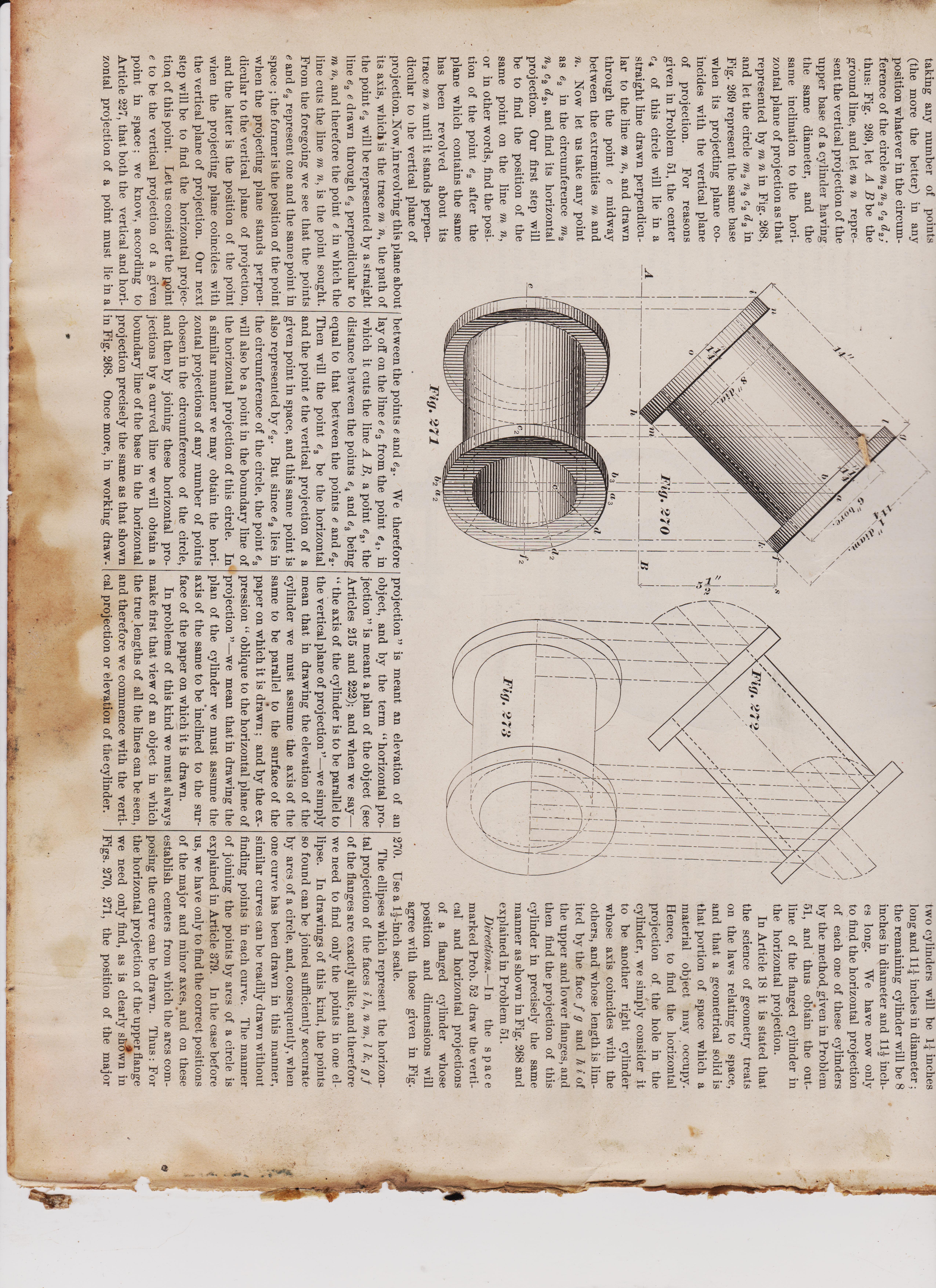
- - Draw any horizontal line A B (Fig. 270).. Since the pointf of the upper flange is to'be 52 inches above the line A B, draw another line f s at a distance of 52 inches above and parallel to A B. The total length of the cylinder (including the flanges) is to be 1.1 inches, therefore from any point h on the line A B as a center, and with a radius of 14 inches, describe a short arc cutting the line f s in the point f, join the points h and f by a straight line; this line will give the correct inclination of the cylinder. From the point on the line h f lay off a point m ; the dis-tance between these points must be equal to the thickness of the flange, namely 11 inches; also on the line h, f lay off, 11 inches from f, a point k. Through the points h, m, k, f; draw lines perpendicular to h f • to do this use the T and set squares in a manner as illustrated in Figs. 71 and 80. Draw the center line a o parallel to, and at a distance of 58 inches from h f ; again at a distance of 58 inches from a o draw the lines i n and l g, which will complete the vertical projection of the flanges. On each side of the center line a o, and parallel to it, draw a straight line ; the distance between the axis and each one of the lines must be 4 inches, making the total distance between these lines equal to the diameter of the cylinder, namely 8 inches. Also indicate the thickness of the metal in the cylinder by drawing two dotted lines, parallel to a o, and each line 3 inches away from a o ; these lines will complete the elevation of the flanged cylinder. In order to find the horizontal projection consider this flanged cylinder to be com-posed of three separate right cylinders (Art. 299) whose axes lie in one straight line and their bases in contact. Two of these separate cylinders will be represented by the flanges, and therefore each one of these two cylinders will be 11 inches long and 111 inches in diameter ; the remaining cylinder will be 8 inches in diameter and 112 inch-es long. We have now only to find the horizontal projection of each one of these cylinders by the method, given in Problem 51, and thus obtain the out-line of the flanged cylinder in the horizontal projection. In Article 18 it is stated that ; the science of geometry treats
***************************************************************************************
taking any number of points (the more the better) in any position whatever in the circum-ference of the circle m2 n2 c2 d2; thus: Fig. 269, let A B be the ground line, and let m n repre-sent the vertical projection of the upper base of a cylinder having the same diameter, and the same inclination to the hori-zontal plane of projection as that represented by m n in Fig. 268, and let the circle m2 n, c2 d2 in Fig. 269 represent the same base when its projecting plane co-incides with the vertical plane of projection. For reasons given in Problem 51, the center C., of this circle will lie in a straight line drawn perpendicu-lar to the line m n, and drawn through the point c midway between the extremities m and n. Now let us take any point as e2 in the circumference m2 n2 c2 d2, and find its horizontal projection. Our first step will be to find the position of the same point on the line m n, or in other words, find the posi-tion of the point e2 after the plane which contains the same has been revolved about its trace m n until it stands perpen-dicular to 1 he vertical plane of projection. Now,inrevolving this plane about its axis, which" is the trace m n, the path of the point e2 will be represented by a straight line e2 e drawn through e2 perpendicular to a,, and therefore the point e in which the line cuts the line m n, is the point sought. From the foregoing we see that the points e and e2 represent one and the same point in space the former is the position of the point when the projecting plane stands perpen-dicular to the vertical plane of projection, and the latter is the position of the point when the projecting plane coincides with the vertical plane of projection. Our next step will be to find the horizontal projec-tion of this point. Let us consider the point e to be the vertical projection of a given point in space ; we know, according to Article 227, that both the vertical and hori-zontal projection of a point must lie in a
/Fig. 272/ between the points e and e2. We therefore lay off on the line e e3 from the point e4, in which it cuts the line A B, a point e3, the distance between the points e4 and e3 being equal to that between the points e and e2. Then will the point es be the horizontal and the point e the vertical projection of a given point in space, and this same point is also represented by e2. But since e2 lies in the circumference of the circle, the point e3 will also be a point in the boundary line of the horizontal projection of this circle. In a similar manner we may obtain the hori-zontal projections of any number of points chosen in the circumference of the circle, and then by joining these horizontal pro-jections by a curved line we will obtain a boundary line of the base in the horizontal projection precisely the same as that shown in Fig. 268. Once more, in working draw- Pig. 273
projection " is meant an elevation of an object, and by the term " horizontal pro-jection " is meant a plan of the object (see Articles 215 and 222); and when we say—" the axis of the cylinder is to be parallel to the vertical plane of projection"—we simply mean that in drawing the elevation of the cylinder we must assume • the axis of the same to be parallel to the surface of the paper on which it is drawn ; and by the ex-pression " oblique to the horizontal plane of projection "—we mean that in drawing the plan of the cylinder we must assume the axis of the same to be *inclined to the sur-face of the paper on which it is drawn. In problems of this kind we must always make first that view of an object in which the true lengths of all the lines can be seen, and therefore we commence with the verti-cal projection or elevation of the cylinder.
two cylinders will be 11 inches long and 111 inches in diameter ; the remaining cylinder will be 8 inches in diameter and 112 inch-es long. We have now only to find the horizontal projection of each one of these cylinders by the method, given in Problem 51, and thus obtain the out-line of the flanged cylinder in the horizontal projection. In Article 18 it is stated that the science of geometry treats on the laws relating to space, and that a geometrical solid is that portion of space which a material object may occupy. hence, to find the horizontal projection of the hole in the cylinder, we simply consider it to be another right cylinder whose axis coincides with the others, and whose length is lim-ited by the face f g and h i of the upper and lower flanges, and then find the projection of this cylinder in precisely the same manner as shown in Fig. 268 and explained in Problem 51. Directions. —In the space marked Prob. 52 draw the verti-cal and horizontal projections of a flanged cylinder whose position and dimensions will agree with those given in Fig. 270. Use a 1I---inch scale. The ellipses which represent the horizon-tal projection of the faces i h, n m, 1 k, g of the flanges are exactly alike, and therefore we need to find only the points in one el-lipse. In drawings of this kind, the points so found can be joined sufficiently accurate by arcs of a circle, and, consequently, when one curve has been drawn in this manner, similar curves can be readily drawn without finding points in each curve. The manner of joining the points by arcs of a circle is explained in Article 379. In the case before us, we have only to find the correct positions of the major and minor axes, :and on these establish centers from which the arcs com-posing the curve can be drawn. Thus : For the horizontal projection of the uppefit flange we need only find, as is clearly shown in Figs. 270, 271, the position of the major e
(((((((((((((((((((((((((((((((((((((((((((((((((((((
Practical Drawing. By J. G. A. MEYER. FORTIETH PAPER.
375. Remarks relating to Problem 51 : It may often appear difficult to find the projections of straight lines, and more so to find the projections of curved lines ; but if we remember that, when we have the projections of two points of a given straight line, its projection is known ; and when we have the projections of several points of a given curve, the projection of the curve is also known ; consequently, we see that many problems can be reduced to very simple ones, in which all difficulties will disappear. Therefore we should be very particular to understand thoroughly the method of find-ing the projections of points in whatever position these may be given, or in whatever curve they may lie. It is the great import-ance of this subject which leads us to make the following remarks, thereby trusting to enable the student to become as familiar as possible with this subject. In Fig. 268 it will be seen that in order to obtain the horizontal projection of the bases we first established a number of points, as f, h, etc., all equal distances apart in the vertical projection of the upper base of the cylinder. In relation to these points, it must be said that it is not necessary to make the distances between these points equal to each other; we did so simply to make the figure appear symmetrically ; neither is it necessary that two points, for instance, such as e2 and f2, should lie in one straight line, drawn perpendicular to the upper base m n of the cylinder; we simply adopted this method to save labor. We will obtain the same curve in the horizontal projection by taking any number of points (the more the better) in any position whatever in the circum-ference of the circle m2 n2 e,d2; thus: Fig. 269, let A B be the ground line, and let m n repre-sent the vertical projection of the upper base of a cylinder having the same diameter, and the same inclination to the hori-zontal plane of projection as that represented by m n in Fig. 268, and let the circle m2 ne c2 d2 in
AMERICAN MACHINIST
straight line drawn perpendicular to the ground line A B; we therefore draw a ver-tical line through the point e, and this line will contain the horizontal projection e3 of the given point. It now only remains to find the distance between the point e3 and the ground line A B. Since e2 represents the given point when its projecting plane coin-cides with the vertical plane of projection, and since the projecting plane is turned around its trace, it follows that when the projecting plane stands perpendicular to the vertical plane of projection, then the distance between the vertical plane of pro-jection and the point will be equal to that ings the ground line A B is not drawn, and therefore, instead of laying off the point e3 from A B, or in other words, measuring its distance from the ground line, we first draw the diameter ma n3, which is the horizontal projection of a diameter parallel to the ver-tical plane of projection, and from the point f, in which the vertical e f5 cuts m3 n., we lay off on the line e f5 the point e3; the dis-tance between these points must, of cour.e, be equal to that between the points e2 and f4; the point f4 being the point in which the line e e2 produced, cuts the diameter m2 n2 drawn parallel to m n. The result will be the same as before. 376. When a right cylinder with a circu-lar base is standing in an oblique position, as shown in Fig. 268, the horizontal pro-jection of each base will be an ellipse. The center line c3 d3 (Fig. 268), which is the longest straight line that can be drawn in the ellipse, is called the major axis ; and the center line m3 na (Fig. 268), which is the shortest line that can be drawn in the ellipse, is called the minor axis. A more precise definition of these axes will be given when we consider the properties of an ellipse.
Problem 52. PRACTICAL APPLICATION OF PROBLEM 51. 377. To FIND THE VERTICAL AND HORIZONTAL PROJECTION OF A FLANGED CYLINDER, THE DIMENSIONS AND POSITION OF THE SAME BEING GIVEN. In this problem it is required to make an elevation and a plan of a flanged cylinder whose diMensions are given in the illustra-tion ; the axis of the cylinder is parallel to the vertical plane of projection, and oblique to the horizontal plane of projection. In order to refresh the student's memory, we will remark that by the term " vertical DECEMBER 31, 1887
- - Draw any horizontal line A B (Fig. 270).. Since the pointf of the upper flange is to'be 52 inches above the line A B, draw another line f s at a distance of 52 inches above and parallel to A B. The total length of the cylinder (including the flanges) is to be 1.1 inches, therefore from any point h on the line A B as a center, and with a radius of 14 inches, describe a short arc cutting the line f s in the point f, join the points h and f by a straight line; this line will give the correct inclination of the cylinder. From the point on the line h f lay off a point m ; the dis-tance between these points must be equal to the thickness of the flange, namely 11 inches; also on the line h, f lay off, 11 inches from f, a point k. Through the points h, m, k, f; draw lines perpendicular to h f • to do this use the T and set squares in a manner as illustrated in Figs. 71 and 80. Draw the center line a o parallel to, and at a distance of 58 inches from h f ; again at a distance of 58 inches from a o draw the lines i n and l g, which will complete the vertical projection of the flanges. On each side of the center line a o, and parallel to it, draw a straight line ; the distance between the axis and each one of the lines must be 4 inches, making the total distance between these lines equal to the diameter of the cylinder, namely 8 inches. Also indicate the thickness of the metal in the cylinder by drawing two dotted lines, parallel to a o, and each line 3 inches away from a o ; these lines will complete the elevation of the flanged cylinder. In order to find the horizontal projection consider this flanged cylinder to be com-posed of three separate right cylinders (Art. 299) whose axes lie in one straight line and their bases in contact. Two of these separate cylinders will be represented by the flanges, and therefore each one of these two cylinders will be 11 inches long and 111 inches in diameter ; the remaining cylinder will be 8 inches in diameter and 112 inch-es long. We have now only to find the horizontal projection of each one of these cylinders by the method, given in Problem 51, and thus obtain the out-line of the flanged cylinder in the horizontal projection. In Article 18 it is stated that ; the science of geometry treats
***************************************************************************************
taking any number of points (the more the better) in any position whatever in the circum-ference of the circle m2 n2 c2 d2; thus: Fig. 269, let A B be the ground line, and let m n repre-sent the vertical projection of the upper base of a cylinder having the same diameter, and the same inclination to the hori-zontal plane of projection as that represented by m n in Fig. 268, and let the circle m2 n, c2 d2 in Fig. 269 represent the same base when its projecting plane co-incides with the vertical plane of projection. For reasons given in Problem 51, the center C., of this circle will lie in a straight line drawn perpendicu-lar to the line m n, and drawn through the point c midway between the extremities m and n. Now let us take any point as e2 in the circumference m2 n2 c2 d2, and find its horizontal projection. Our first step will be to find the position of the same point on the line m n, or in other words, find the posi-tion of the point e2 after the plane which contains the same has been revolved about its trace m n until it stands perpen-dicular to 1 he vertical plane of projection. Now,inrevolving this plane about its axis, which" is the trace m n, the path of the point e2 will be represented by a straight line e2 e drawn through e2 perpendicular to a,, and therefore the point e in which the line cuts the line m n, is the point sought. From the foregoing we see that the points e and e2 represent one and the same point in space the former is the position of the point when the projecting plane stands perpen-dicular to the vertical plane of projection, and the latter is the position of the point when the projecting plane coincides with the vertical plane of projection. Our next step will be to find the horizontal projec-tion of this point. Let us consider the point e to be the vertical projection of a given point in space ; we know, according to Article 227, that both the vertical and hori-zontal projection of a point must lie in a
/Fig. 272/ between the points e and e2. We therefore lay off on the line e e3 from the point e4, in which it cuts the line A B, a point e3, the distance between the points e4 and e3 being equal to that between the points e and e2. Then will the point es be the horizontal and the point e the vertical projection of a given point in space, and this same point is also represented by e2. But since e2 lies in the circumference of the circle, the point e3 will also be a point in the boundary line of the horizontal projection of this circle. In a similar manner we may obtain the hori-zontal projections of any number of points chosen in the circumference of the circle, and then by joining these horizontal pro-jections by a curved line we will obtain a boundary line of the base in the horizontal projection precisely the same as that shown in Fig. 268. Once more, in working draw- Pig. 273
projection " is meant an elevation of an object, and by the term " horizontal pro-jection " is meant a plan of the object (see Articles 215 and 222); and when we say—" the axis of the cylinder is to be parallel to the vertical plane of projection"—we simply mean that in drawing the elevation of the cylinder we must assume • the axis of the same to be parallel to the surface of the paper on which it is drawn ; and by the ex-pression " oblique to the horizontal plane of projection "—we mean that in drawing the plan of the cylinder we must assume the axis of the same to be *inclined to the sur-face of the paper on which it is drawn. In problems of this kind we must always make first that view of an object in which the true lengths of all the lines can be seen, and therefore we commence with the verti-cal projection or elevation of the cylinder.
two cylinders will be 11 inches long and 111 inches in diameter ; the remaining cylinder will be 8 inches in diameter and 112 inch-es long. We have now only to find the horizontal projection of each one of these cylinders by the method, given in Problem 51, and thus obtain the out-line of the flanged cylinder in the horizontal projection. In Article 18 it is stated that the science of geometry treats on the laws relating to space, and that a geometrical solid is that portion of space which a material object may occupy. hence, to find the horizontal projection of the hole in the cylinder, we simply consider it to be another right cylinder whose axis coincides with the others, and whose length is lim-ited by the face f g and h i of the upper and lower flanges, and then find the projection of this cylinder in precisely the same manner as shown in Fig. 268 and explained in Problem 51. Directions. —In the space marked Prob. 52 draw the verti-cal and horizontal projections of a flanged cylinder whose position and dimensions will agree with those given in Fig. 270. Use a 1I---inch scale. The ellipses which represent the horizon-tal projection of the faces i h, n m, 1 k, g of the flanges are exactly alike, and therefore we need to find only the points in one el-lipse. In drawings of this kind, the points so found can be joined sufficiently accurate by arcs of a circle, and, consequently, when one curve has been drawn in this manner, similar curves can be readily drawn without finding points in each curve. The manner of joining the points by arcs of a circle is explained in Article 379. In the case before us, we have only to find the correct positions of the major and minor axes, :and on these establish centers from which the arcs com-posing the curve can be drawn. Thus : For the horizontal projection of the uppefit flange we need only find, as is clearly shown in Figs. 270, 271, the position of the major e
33333333333third
pic bott
\
pic bott


3rd scan AMERICAN-MACHINIST-1889 page 1
3333333333334 AMERICAN MACHINIST DECEMBER 31, 1887
Instructions for Making Patterns from Models, Templets, Plaster Casts, Carved Blocks, Etc.
BY S. BOLLAND.
We will first consider what can be done with the templet and strickle. Fig. 1 is the sketch of a section of top and bottom railing about 9" wide and 1" thick all over. These are made in various lengths, some straight and others curved at one end. A few hours, at most, will serve to make such a pattern as this by the method under con-sideration, the only outlay for pattern work being the strickle and templet on which it is to travel. First consider a straight piece of pattern, say six feet long, and to the di-mensions given for Fig. 1. Let it be the top half. By referring to Fig. 2 it will be seen at a glance. Such as this can be made readily in a flask by securing parallel pieces (planed to a true surface) on the edges of the flask, as seen at A. The strickle is shown resting on these pieces, with stop B at one end, to guide it straight. The first thing to be done is to ram the sand very hard in the flask, and strike off the form of top side of parttern ; this is the • line marked C on the strickle. If this is carefully done a true and hard surface is the result. Smooth over and dust on the parting sand, taking care to have no more on than is necessary to part the cope. Let the cope be evenly rammed on this and lifted away. Before proceeding to strike out the thickness the bed must be prepared, as in this condition 'it would be altogether too hard for the iron to rest on. After such preparation is made, then strike off the thickness, as shown at line marked D. I have shown a space outside the web at E. This is to aid in securing a good inner edge when the web is deep, leaving the outside to be made up with a piece of pattern the thickness required. All that is needed now is the right man to finish up the mould—one who has made the use of his tools a study. Such a man will turn out a pattern by this method, equal in every respect to the one made from a wooden model ; in fact, very often much superior, as there is always great difficulty in keeping such light patt erns in shape. Of course blocks can be made to fit them, but this is only adding still more expense ; and why incur all this
but when properly done a good impression can be had. When the cope is lifted off, the templet must be replaced, and after the requisite preparations for venting, etc , have been made, proceed to ram the core, and with strickle No. 2 (which must have the required thickness allowed when made) proceed as directed for the outside. I may be pardoned for again saying that unless a first-class workman be entrusted with this kind of work, good results cannot ensue, as there are so many points to be watched, such as the even ramming, correct finish, and an eye at all times to the draft required to insure a smooth working pat-tern. Although I have not shown ends on the templet at Fig. 3, they can be put on when it is thought advantageous. It will at once be seen that this method may be applied to a wide range of work, and that it costs comparatively nothing for pattern making.
Fig. 1. Fig. C. Fig. 5.
gives less trouble. in ramming, and, secures a better core with less labor. It is right to say here that when method shown at Fig. 6 is adopted, the ends must be of the same diameter as the inside of pattern. Numerous illustrations might be given to show the adaptibility of this method to the production of other circular patterns, but I feel sure that enough has been said to prove its adequacy; for by slight modifications of the system, almost every emergency may be met successfully. We will now consider the subject of mak-ing cast patterns from models, plaster casts and carved blocks. Fig. 7 is the sketch of a newel post, quite a familiar object, and needs no explanation. My reasons for selecting this post is because it furnishes cap ital opportunities for illustrating the method of making patterns from carved blocks. This post is supposed to be 12" square at the base and cap, and 3' high; such a post is usually made up of four thin slabs about 1" thick, mitered at the corners, and held together by internal fast-enings. Being sold at so much apiece, it of course behooves the founder to keep therri as light as pos-sible, especially as com-petition in their manufac-ture is very keen. In fact, however massive any of this class of work may seem, we may rest assured that it is just as thin gs the manufacturer knew how to make it. Some of this work is really handsome, and tests the skill of the carver to produce it, but carving out the face side is not the whole difficulty. If (as is sometimes attempted) the back is cut out to the de-sired thickness all over, the chances are that some parts will be cut through, whilst other parts will not be cut deep enough; and to avoid the former evil, it is considered best --fig. 4.
_Fig. 7.
the block and proceed to lay in the thick-ness, which will be made of clay, after this manner : The best clay for the purpose is the red, smooth kind ; dry it and pound fine ; then sift through a fine sieve and wet to the consistency of stiff putty. Now nail two strips I" thick on a smooth board, as far apart as required, and roll out the clay between. All that is now needed is a knife and a little ingenuity, and the clay may be cut and laid on the hard mould with the greatest accuracy, every part of the surface being correct to thickness. It will now 1w seen why the bottom was to be rammed so hard the first time, and also why the joint was to be extended past the feather edge ; in thy` latter case, the thickness can stand past the edge a little when laid on, and pared off even with the joint afterwards. Now prepare for parting, and take this impression in cope No. 2. (This will be the top part of mould and the back of pattern.) Should there be intricate parts in the lift, clamp the two parts together and roll them both back on a soft bed. You can now loosen the nowel and lift the sand away carefully without disturbing any of the mould in the cope. When the clay is re-moved you have, a perfect impression. In finishing this, be careful to give good draft where it is needed. The necessity of cope No. 1 is now seen, for the joint in this is the same impress as that in cope No. 2, and nothing remains to be done but to place in the back, bring on the Dowel and ram so as to give a good, even casting. When this is turned over, cope No. 1 ends its usefulness by leaving you the joint exactly corresponding with the impression taken in cope No. 2, so that you have an absolute fit when they are placed together, and an even thickness at every part of the pattern. Should the design be very elaborate, with many delicate edges, it will facilitate the thicknessing very much if a coat of plaster be run over the pattern instead of the hard ramming as directed, thus leaving a good hard face to lay the clay to. This is the best where there is very fine carving, and the pattern is to be extra light, such as for ornaments, fine mouldings and all patterns for decorative purposes. When the model covers a large space it is customary for the designer to have it cast in plaster sections to insure easy and safe shipments. To make a pattern from such set.-
WICKES ~ BROTHERS
220 Water Street, Saginaw, Mich.
801 Fifth Ave., New York 736 White- Henry Bldg., Seattle, Wash.
4. AMERICAN-MACHINIST-1922-page 2 January-5-Vol-56-No 1

555555555 5th AMERICAN-MACHINIST-Dec 31 1887 page 5 DECEMBER 31, 1887 AMERICAN MACHINIST
nowel was lifted to be rammed on cope No. 2.
I shall be excused, I think, for so much apparent repetition in these instructions, because I know that, to those who have had no experience in this class of work, there seems more or less mystery in the use of two copes; but a little thought will over-come all this and the whole thing appear in all its simplicity. To foundries where no pattern makers are employed a knowledge of the methods is indispensable, as it places them (so far as this class of work is con-cerned) on an equal footing with the best equipped firms. To conclude I would say that many in-genious contrivances will suggest them-selves to the moulder engaged on this line of work ; as, for instance, a rough block with bearings for a strickle to work on can be struck off in plaster to any design which runs the same along its whole length ; this can be used as a model and backed out with clay thickness as directed. All such patterns as are shown at Fig. 1 can be treated this way, thereby enabling the moulder to choose either the method ex-plained at Fig, 2 or the one just considered. In fact, this article is but a mere outline of what can be done by these methods ; for when once entered into it will be found that scarcely any limit can be placed to its use fulness.
Good Advice. In the copy of the constitution and by-laws of a mutual benefit association sent us by Bausch & Lomb Optical Co., of Roch-ester, N. Y., is a loose leaf not belonging to the copy referred to. From this leaf we learn that this firm has established a library consisting of books, newspapers, periodicals, etc.. for the use of their employes. On this leaf are printed a few very simple rules to be observed by those making use of the library—rules in which any intention to hedge about the use of the library by annoy-ing conditions is conspicuously absent. Then follows this advice, which is worthy of being given wide publicity. We think nothing better could be got into the same space: "Read something useful every day, if only for a few minutes. gineers. Regular meetings will be held at stated intervals, at which papers will be read and topics relating to foundry practice discussed. Following are the offic, rs of the new society : President, Isaac Wirclaester, of Boston ; vice-presidents, N. Balton of Norwich, Conn., R. H. Palmer, of Provi-dence, R. I. ; secretary, J. P. Pero, Stam-ford, Conn.; treasurer, Frank Gibby, Boston, Mass.; councilors, Frank Davey, Bristol, Conn., Joseph Hennessey, Chicopee Falls, Mass.; managers, J. B. Pero ,'Indian Orchard, Mass.; Jno. Witherell, Florence, Mass.; Thos. King, Meriden, Conn.; J. S. Richardson, Rutland, Vt.; H. B. Murless, Rockville, Conn. The next meeting of the society will be at Worcester, Mass., July 2.
A Good Appointment. Charles A. Bauer, general manager of the Wardner, Bushnell & Glessner Works, at Springfield, Ohio, has been appointed one of the commission( rs of the machinery depart-ment of the forthcoming centennial of Ohio. The officers of the department of machinery should receive credit for appointing a man of Mr. Bauer's well-known mechanical and business ability to this place. Such appoint-ments will go a long way towards establishing confidence in the enterprise, and are in pleas-ing con*rast to those sometimes made for similar purposes. Mr. Robert' E. Masters, well known to our readers, has accepted a new position. The following, from the Richmond Whig, will explain : **Mr. Robert E. Masters has been ap-pointed general superintendent of the Marshall Car Wheel and Foundry Com-pany's plant at Marshall, Texas, and in con-sequence has resigned his position as man-ager of the cast-iron de_ partment of the Tredegar 9 Iron Works, to take effect on the 31st of this month. ‘-‘ As an expert in the mixture of metals and in the management of men and work pertaining to foundry practice, Mr. Masters is said to have no superior. His practical, illustrated articles in the A mEiticAN MA- O States in 1886. We call attention to this fact, because there is nothing in the way measuring is done by ordinary mortals in this country to-day, to remind them of it, and they might lose sight of it. There is always the old difference between leading a horse to water and making him drink.
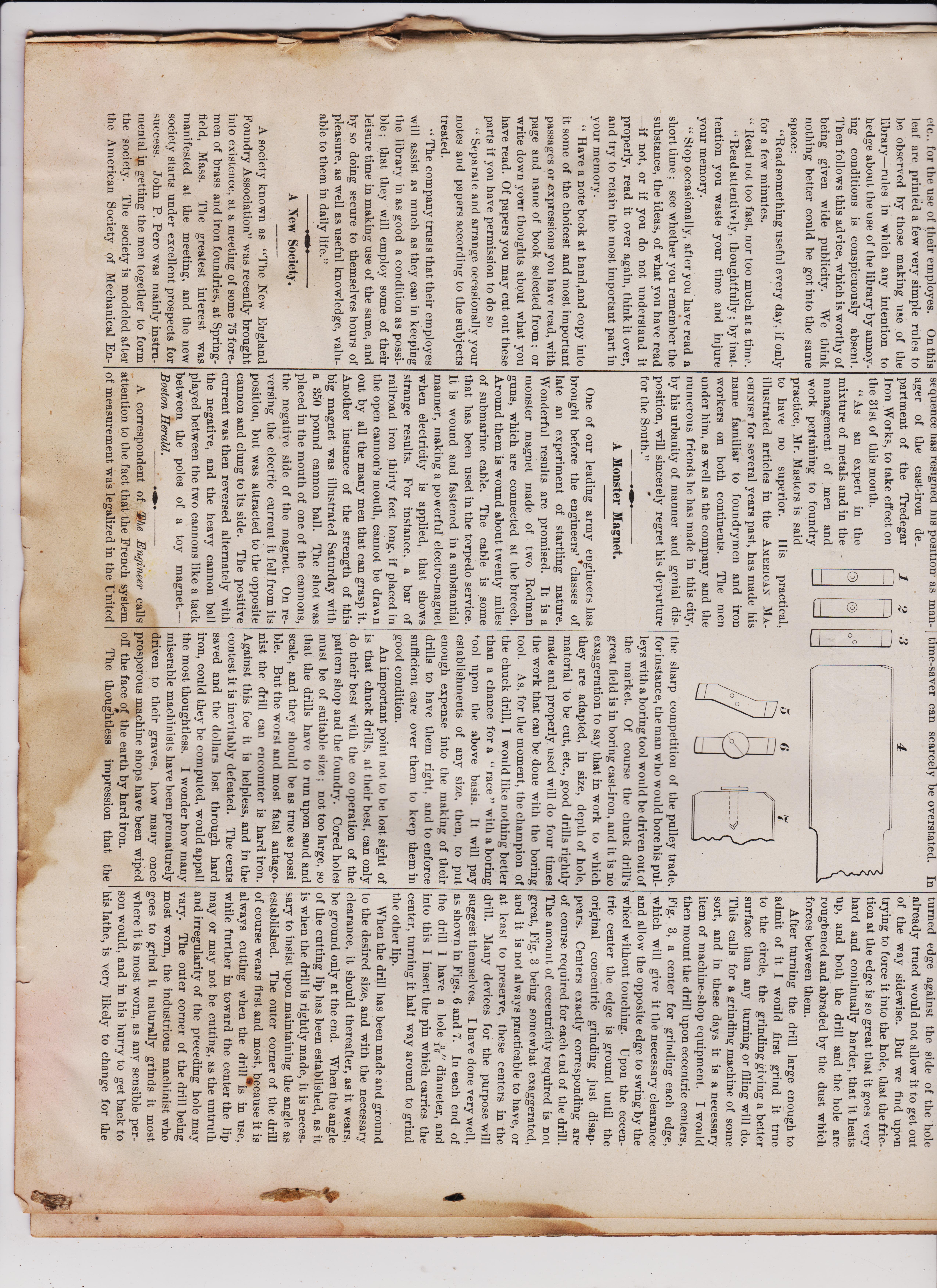
Something About Chucking Drills. BY FRANK H. RICHARDS. The makers of small machine tools—the successful and established makers — ac-complish a great good for the trade other than that which arises directly from the diffusion of their own products. They do much to raise the general standard of ex-cellence in such articles. The taps and drills and reamers offered ready-made to our hands to-day are so good that even those that we make for ourselves are better than those we would have made or expected twenty years ago. The ideas of the trade are unconsciously enlarged con-tinually, and the criterion of means and of accomplishment becomes more exacting. There are no articles that I think of that are better in their way than the reamers of the best makers. Taps are by no means so satisfactory. Years ago I used to find chuck or chuck-ing drills advertised ; lately I have been looking through a number of trade cata-logues and have not discovered them any-where. I suppose that when they have been offered to the trade there has not been much sale for themlbecause they are such a simple article. Anybody can make a chuck drill, is the general impression ; con-sequently anybody and everybody do make them, and we find them scattered through our shops in every grade of inefficiency. The importance of the chuck drill as a time-saver can scarcely be overstated. In points" of the chuck (bill are unim-portant, and that anything that can be crowded through a hole is good enough, is far from the actual fact. I believe, and am Prepared to maintain, that the chuck drill requires as much care and skill in the mak-ing as most tools, and that to maintain it in good condition and efficiency calls for unusual resolution and vigilance. Chuck drills should generally be used in sets of three. For some small work in clean and true castings two will do very well. The first drill wears much faster than the others, but should be kept sharp and true, as the more it does toward straightening and truing the hole the better it will he for the others, and the more satisfactory the final result. The first drill should do the heaviest cutting, while very little should be left for the last, so that it may maintain its size and not throw too much work upon the reamer which is to follow it. The chuck drill should be forged flat, usually of an uniform thickness through-out its length, and with the head large enough to be turned to the desired size anu the remainder of the drill small enough to pass freely into the hole it bores. The head may be in length three times the diameter, when it may be worn back twice the diameter before renewing. The drills should b e turned, each to its required size, perfectly straight and true, and square at the end, the cutting corner beveled as wide as the expected cut, and this beveled corner filed or ground back enough to give it clearance, and the drill then hardened The drill, Fig. 1, will then be in the best possible condition for boring a true hole. The only objection to it is that it will not work. If it could be once started true it must make a hole nearly true to any reasonable depth, for its turned edge against the side of the hole already trued would not allow it to get out of the way sidewise. But we find upon, trying to force it into the hole, that the friction at the edge is so great that it goes very hard and continually harder, that it heats up, and both the drill and the hole are roughened and abraded by the dust which forces between them. After turning the drill large enough to admit of it I would first grind it true to the circle, theffrindino hit ter


