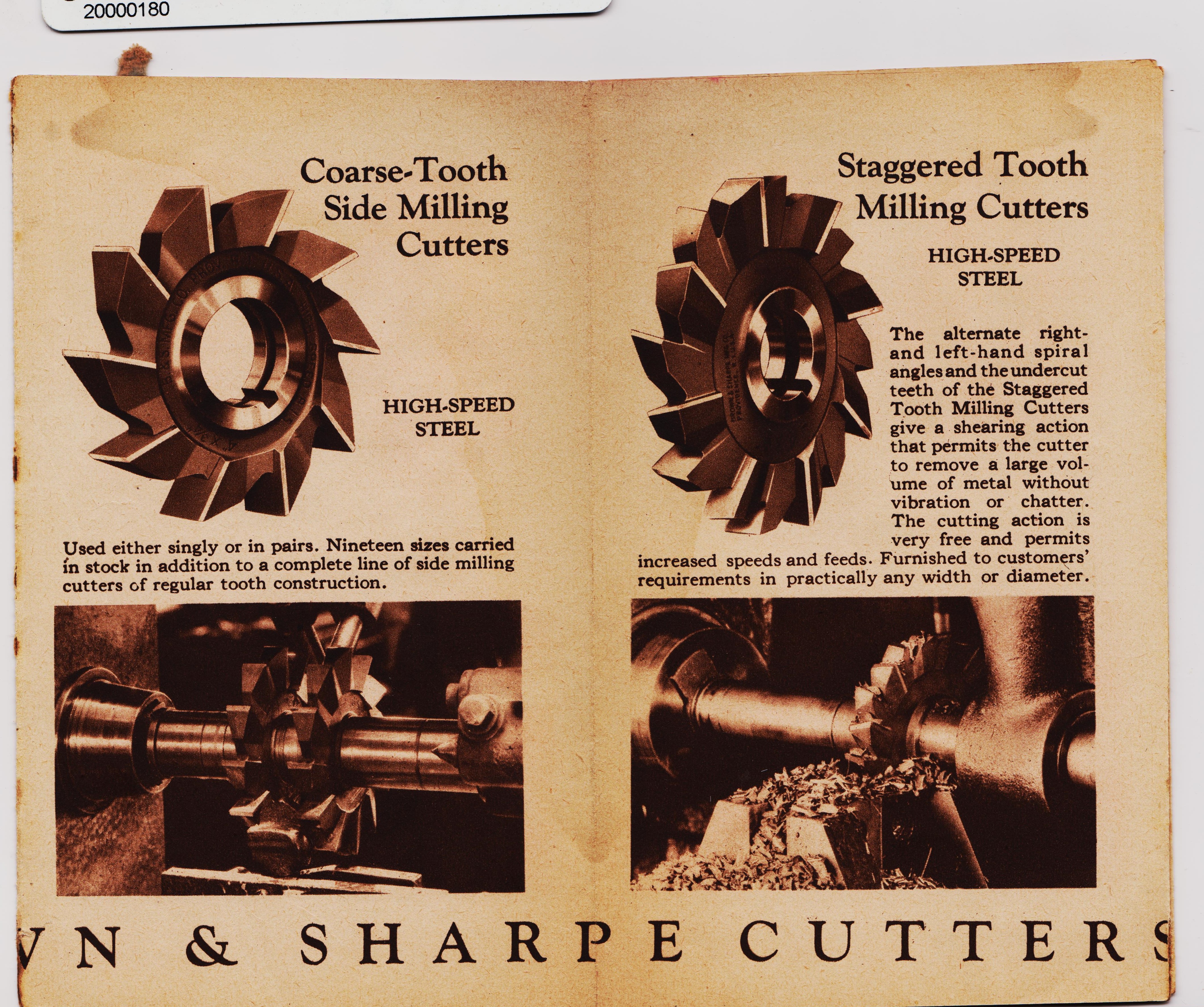
top
top
sky
pic top
size
title pic
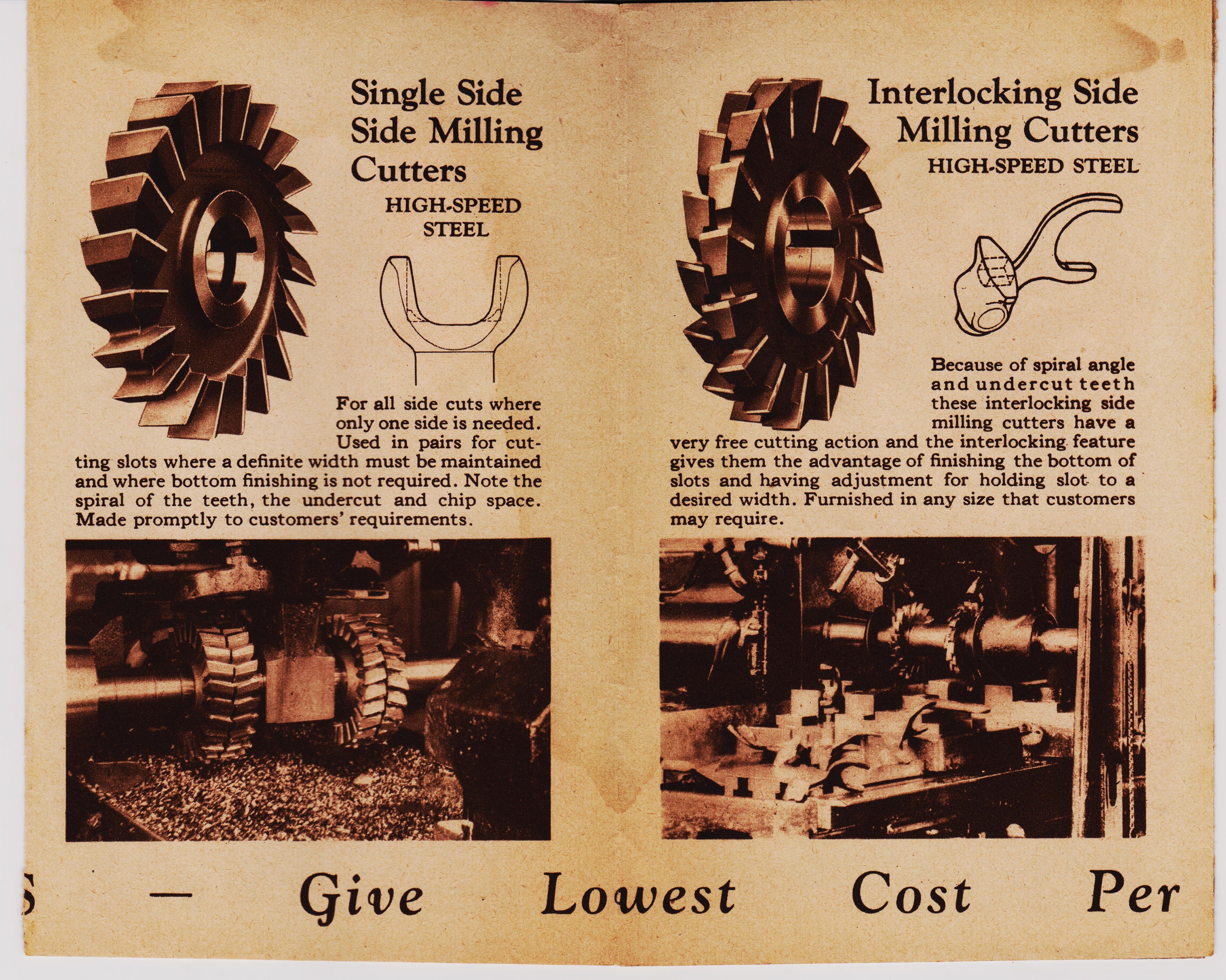
top
sky
pic top
size

top
top
sky
pic top
size
top
sky
pic top
size
Party Like Its 1929, What is life like for your family when this was the new teck life?
First World War erupts. ..The St. Valentine's Day Massacre on February 14th.
..............Yes, Violence can effect change............Just maybe not the change you tried for.
What was 1929 like? In 1929 the economy began to slow down. At the end of October, panic gripped the stock market and people began to sell massive amounts of stock. The worst days were October 28th and 29th when values fell a total of 23%. These days became known as "Black Monday" and "Black Tuesday.
1. Leading up to the crash the United States experiences an economic boom during the 1920's. Many investors are speculators and the stock market keeps growing starting around 1923.
2. The stock market experiences a mini-crash on March 25th as investors start to sell their stocks. This crash reveals a shaky foundation in the market. Borrowing and credit is effected as interest rates climb to twenty percent.
3. Banker Charles E. Mitchell pledges $25 million in credit to stop the stock market slide a few days after the mini-crash. He is called upon to leave his post on the Federal Reserve Board for his interference with the market. Come on Biden man.
4. The economy shows signs of slowing as steel production, construction and car sales all experience decline during the spring. However, the stock market keeps climbing breaking records month after month, despite the signs of strain.
8. Black Monday happens on October 28th, when the U.S. stock market experiences its biggest drop in history, 22.6% in one day. This crash begins to influence other markets around the world. 9. Black Tuesday happens on October 29th, as panicked investors begin to sell all their stocks. The stock market drops another 12.8% by the end of the day.
11. The U.S. joins the rest of the world in the Great Depression as massive amounts of people become unemployed and the economy loses incomprehensible amounts of money due to the stock market crash. The Great Depression lasts until World War II begins.
12. In 1932, the U.S. stock market reaches its lowest point when it closes 89 percent down from its highest point .
main text at top Machinist machinery March 1896
First World War erupts. ..The St. Valentine's Day Massacre on February 14th.
..............Yes, Violence can effect change............Just maybe not the change you tried for.
What was 1929 like? In 1929 the economy began to slow down. At the end of October, panic gripped the stock market and people began to sell massive amounts of stock. The worst days were October 28th and 29th when values fell a total of 23%. These days became known as "Black Monday" and "Black Tuesday.
1. Leading up to the crash the United States experiences an economic boom during the 1920's. Many investors are speculators and the stock market keeps growing starting around 1923.
2. The stock market experiences a mini-crash on March 25th as investors start to sell their stocks. This crash reveals a shaky foundation in the market. Borrowing and credit is effected as interest rates climb to twenty percent.
3. Banker Charles E. Mitchell pledges $25 million in credit to stop the stock market slide a few days after the mini-crash. He is called upon to leave his post on the Federal Reserve Board for his interference with the market. Come on Biden man.
4. The economy shows signs of slowing as steel production, construction and car sales all experience decline during the spring. However, the stock market keeps climbing breaking records month after month, despite the signs of strain.
8. Black Monday happens on October 28th, when the U.S. stock market experiences its biggest drop in history, 22.6% in one day. This crash begins to influence other markets around the world. 9. Black Tuesday happens on October 29th, as panicked investors begin to sell all their stocks. The stock market drops another 12.8% by the end of the day.
11. The U.S. joins the rest of the world in the Great Depression as massive amounts of people become unemployed and the economy loses incomprehensible amounts of money due to the stock market crash. The Great Depression lasts until World War II begins.
12. In 1932, the U.S. stock market reaches its lowest point when it closes 89 percent down from its highest point .
Brown and Sharpe Mfg Co. 1929
Set up and use the No. 2 Brown & Sharp
Universal Reamer and Cutter Grinder.
You will see how precise grinding should be set up
and done in WWl-to-1929 and still can today with these still useful machines.
All these machines require is a bit more time and skill but less $$.
Set up and use the No. 2 Brown & Sharp
Universal Reamer and Cutter Grinder.
You will see how precise grinding should be set up
and done in WWl-to-1929 and still can today with these still useful machines.
All these machines require is a bit more time and skill but less $$.


1929
The Brown & Sharpe Mfg. Co., occupies at the present time ten fireproof manufacturing buildings, having a floor area of over 1,397,000 square feet, or approximately 32 acres. This plant is the outgrowth of the small shop in which the business started in 1833 and which it outgrew in 1872. The works are located but a short distance from the business center of Providence and visitors are always welcome. The Nos. 2 and 3 Cutter Grinding Machines may be seen at the plant in the course of construction or actually at work under manufacturing conditions. %%%%%%%%%%%%%%%%% page6

text pg 8
text pg 7

text pg 8
text pg 9
text pg 12
 %%%%%%%%%
page 13
%%%%%%%%%
page 13

text pg 13

text pg 14
text pg 15
text pg 15

text pg 16
text pg 16

text pg 17

text pg 18
text pg 18

text pg 19

text pg 20
text pg 20
text pg 23
text pg 23
text pg 22
text pg 23
text pg 24
text pg 24
text pg 25
text pg 25
text pg 26
text pg 26
text pg 27
text pg 27

text pg 28
text pg 28

text pg 29
text pg 29

text pg 30
text pg 30
text pg 32
text pg 32

text pg 32
text pg 32
 title text
width="843" height="784" alt="">
11 pic down text
title text
width="843" height="784" alt="">
11 pic down text
 &&&&&&&&&&&&&&&&&&&&&&&&&&
130 add
&&&&&&&&&&&&&&&&&&&&&&&&&&
130 add
 &&&&&&&&&&&&&&&&&&&&&&&&&&&&&
12 page top pg 203 helical 18700
&&&&&&&&&&&&&&&&&&&&&&&&&&&&&
12 page top pg 203 helical 18700
 &&&&&&&&&&&&&&&&&
title text
width="843" height="784" alt="">
11 pic down text
&&&&&&&&&&&&&&&&&
title text
width="843" height="784" alt="">
11 pic down text
 title text
width="843" height="784" alt="">
11 pic down text
title text
width="843" height="784" alt="">
11 pic down text
 width="843" height="784" alt="">
11 pic down text
width="843" height="784" alt="">
11 pic down text
 width="843" height="784" alt="">
11 pic down text
+++++++++++++++++++++++++++++++++++++++++++++++
width="843" height="784" alt="">
11 pic down text
+++++++++++++++++++++++++++++++++++++++++++++++
 width="843" height="784" alt="">
11 pic down text
11 pic down text
width="843" height="784" alt="">
11 pic down text
11 pic down text
 width="843" height="784" alt="">
11 pic down text
width="843" height="784" alt="">
11 pic down text
 width="843" height="784" alt="">
11 pic down text
+++++++++++++++++++
11 pic down text
width="843" height="784" alt="">
11 pic down text
+++++++++++++++++++
11 pic down text
width="843" height="784" alt="">
11 pic down text
+++++++++++++++++++
11 pic down text
width="843" height="784" alt="">
11 pic down text
+++++++++++++++++++
11 pic down text
 width="1092" height="759"
alt=""
>
11 pic down text
$$$$$
width="1092" height="759"
alt=""
>
11 pic down text
$$$$$
 width="1092" height="759"
alt="">
11 pic down text
$$$$
width="1092" height="759"
alt="">
11 pic down text
$$$$
 width="900" height="600"
alt="">
11 pic down text
^^^^^^^^^^^^^^^^^^^^^^^^^^^^^^^^^^^^^^^^^^^^^^^^^^^^
old pic last amer mach
width="900" height="600"
alt="">
11 pic down text
^^^^^^^^^^^^^^^^^^^^^^^^^^^^^^^^^^^^^^^^^^^^^^^^^^^^
old pic last amer mach
The Brown & Sharpe Mfg. Co., occupies at the present time ten fireproof manufacturing buildings, having a floor area of over 1,397,000 square feet, or approximately 32 acres. This plant is the outgrowth of the small shop in which the business started in 1833 and which it outgrew in 1872. The works are located but a short distance from the business center of Providence and visitors are always welcome. The Nos. 2 and 3 Cutter Grinding Machines may be seen at the plant in the course of construction or actually at work under manufacturing conditions. %%%%%%%%%%%%%%%%% page6
How to set up and use Universal Cutter Grinder Machines, B&S Co. printed 1929.
page 6
BROWN & SHARPE MFG. CO.
DRAWING THE TEMPER.
There will be no danger of drawing the temper of the cutter teeth if reasonable care is taken not to grind off too much stock at each contact with the wheel. It is a good plan at first, to make a few movements of the cutter before starting the grinding wheel. Do not exert too much pressure on the cutter as it passes across the wheel; this is a common error and may burn the teeth of the cutter.
A FIG. 1
Grinding Clearance of Teeth CLEARANCE.
The clearance of the teeth back of the cutting edges is obtained, (when the teeth face downward) by having the center of the cutter lower than the center of the wheel, as at A Fig. 1. When the teeth point upward as at B, the center of the work should be above the center of the wheel. The angle of clearance depends upon the diameter of the cutter; it should be greater for small cutters than for large ones. The clearance on the teeth of plain milling cutters should be from 4 to 5 degrees for cutters larger than 3 inches in diameter, and from 6 to 7 degrees for those smaller than 3 inches. The land at the top of the teeth should be from .02 " to .04 " wide before the clearance is ground. The clearance on the end teeth of end mills should be about 2 degrees and it is an advantage to have the teeth somewhat "hollowing"; about .001 " to .002 " lower near the center than on the outside, so that the inner ends of the teeth will not drag on the work. Too much clearance tends to cause chatter or vibration and should be avoided.
page7
page 6
BROWN & SHARPE MFG. CO.
DRAWING THE TEMPER.
There will be no danger of drawing the temper of the cutter teeth if reasonable care is taken not to grind off too much stock at each contact with the wheel. It is a good plan at first, to make a few movements of the cutter before starting the grinding wheel. Do not exert too much pressure on the cutter as it passes across the wheel; this is a common error and may burn the teeth of the cutter.
A FIG. 1
Grinding Clearance of Teeth CLEARANCE.
The clearance of the teeth back of the cutting edges is obtained, (when the teeth face downward) by having the center of the cutter lower than the center of the wheel, as at A Fig. 1. When the teeth point upward as at B, the center of the work should be above the center of the wheel. The angle of clearance depends upon the diameter of the cutter; it should be greater for small cutters than for large ones. The clearance on the teeth of plain milling cutters should be from 4 to 5 degrees for cutters larger than 3 inches in diameter, and from 6 to 7 degrees for those smaller than 3 inches. The land at the top of the teeth should be from .02 " to .04 " wide before the clearance is ground. The clearance on the end teeth of end mills should be about 2 degrees and it is an advantage to have the teeth somewhat "hollowing"; about .001 " to .002 " lower near the center than on the outside, so that the inner ends of the teeth will not drag on the work. Too much clearance tends to cause chatter or vibration and should be avoided.
How to set up and use Universal Cutter Grinder Machines, B&S Co. printed 1929.
page 7
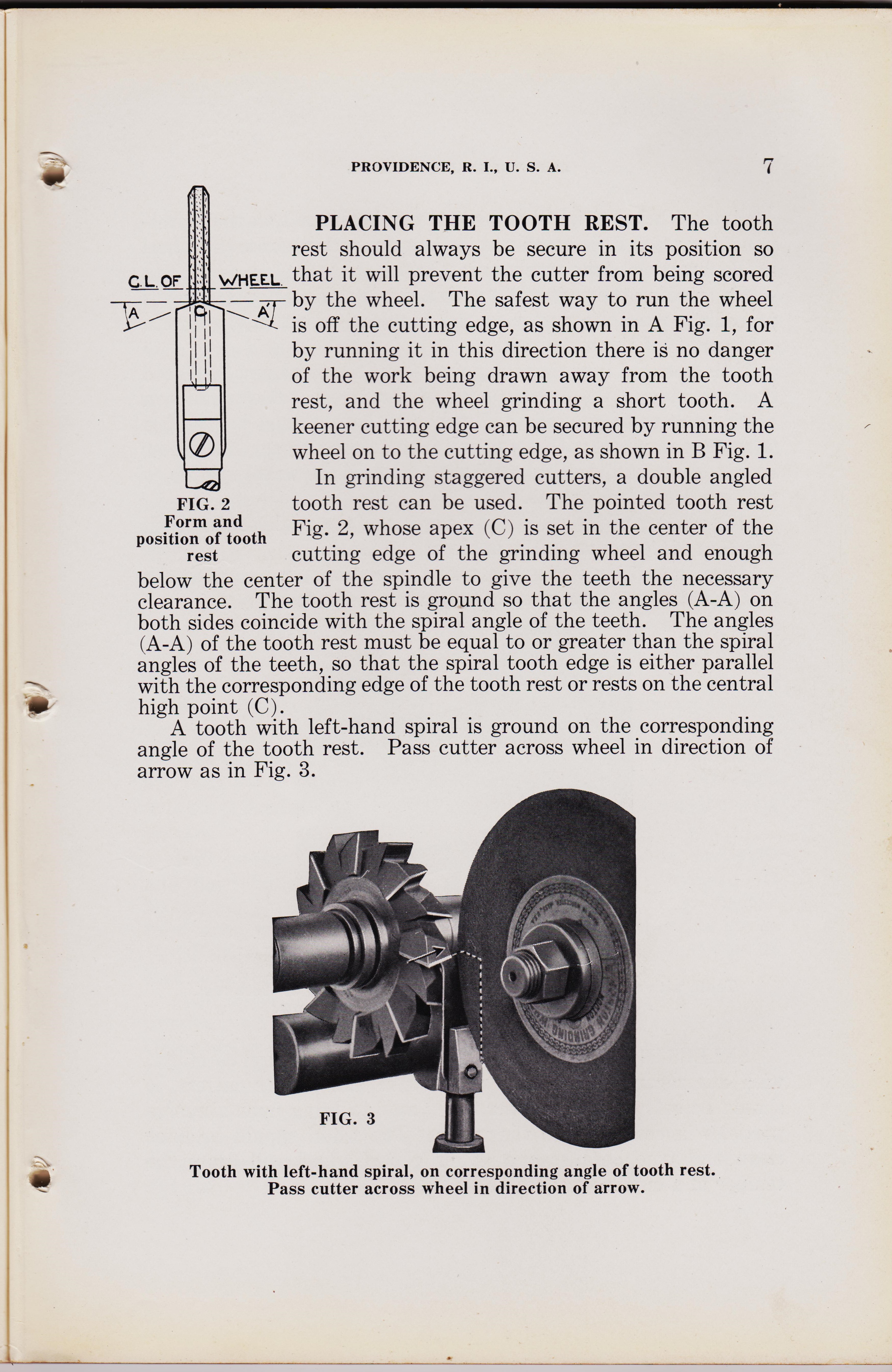
BROWN & SHARPE MFG. CO.
PROVIDENCE, R. I., U. S. A.
PLACING THE TOOTH REST. The tooth rest should always be secure in its position so viHEEL that it will prevent the cutter from being scored
C. L. OF
A AZ by the wheel. The safest way to run the wheel is off the cutting edge, as shown in A Fig. 1, for by running it in this direction there is no danger of the work being drawn away from the tooth rest, and the wheel grinding a short tooth. A keener cutting edge can be secured by running the wheel on to the cutting edge, as shown in B Fig. 1. In grinding staggered cutters, a double angled tooth rest can be used. The pointed tooth rest Fig. 2, whose apex (C) is set in the center of the cutting edge of the grinding wheel and enough below the center of the spindle to give the teeth the necessary clearance. The tooth rest is ground so that the angles (A-A) on both sides coincide with the spiral angle of the teeth. The angles (A-A) of the tooth rest must be equal to or greater than the spiral angles of the teeth, so that the spiral tooth edge is either parallel with the corresponding edge of the tooth rest or rests on the central high point (C). A tooth with left-hand spiral is ground on the corresponding angle of the tooth rest. Pass cutter across wheel in direction of arrow as in Fig. 3.
FIG. 2
Form and position of tooth rest
Tooth with left-hand spiral, on corresponding angle of tooth rest. Pass cutter across wheel in direction of arrow.
7777777777777777777
page 8
page 7
BROWN & SHARPE MFG. CO.
PROVIDENCE, R. I., U. S. A.
PLACING THE TOOTH REST. The tooth rest should always be secure in its position so viHEEL that it will prevent the cutter from being scored
C. L. OF
A AZ by the wheel. The safest way to run the wheel is off the cutting edge, as shown in A Fig. 1, for by running it in this direction there is no danger of the work being drawn away from the tooth rest, and the wheel grinding a short tooth. A keener cutting edge can be secured by running the wheel on to the cutting edge, as shown in B Fig. 1. In grinding staggered cutters, a double angled tooth rest can be used. The pointed tooth rest Fig. 2, whose apex (C) is set in the center of the cutting edge of the grinding wheel and enough below the center of the spindle to give the teeth the necessary clearance. The tooth rest is ground so that the angles (A-A) on both sides coincide with the spiral angle of the teeth. The angles (A-A) of the tooth rest must be equal to or greater than the spiral angles of the teeth, so that the spiral tooth edge is either parallel with the corresponding edge of the tooth rest or rests on the central high point (C). A tooth with left-hand spiral is ground on the corresponding angle of the tooth rest. Pass cutter across wheel in direction of arrow as in Fig. 3.
FIG. 2
Form and position of tooth rest
Tooth with left-hand spiral, on corresponding angle of tooth rest. Pass cutter across wheel in direction of arrow.
How to set up and use Universal Cutter Grinder Machines, B&S Co. printed 1929.
page 8
BROWN & SHARPE MFG. CO.
A tooth with a right-hand spiral can be ground on the corres-ponding angle of the tooth rest. Pass the cutter across the wheel in the direction of the arrow as in Fig. 4. In grinding the next tooth with a spiral angle, alternate to the preceding, pass the cutter in the opposite direction, using the other angle of the tooth rest. It is essential that the high point (C) of the tooth rest be placed in the center of the cutting edge of the wheel. Best results in getting the teeth ground uniformly will be obtained by using a fairly narrow wheel with not over 8 inch cutting edge. The cutter should be set sufficiently below the center of the wheel spindle to give the desired clearance. In grinding the spiral cutting edges, use the angle of the tooth rest that corresponds to the angle of the tooth. Pass the cutter across the wheel with the spiral edge of the tooth resting on the corresponding angle of the tooth rest.
Tooth with right-hand spiral, on corresponding angle of tooth rest. Pass cutter across wheel in direction of arrow.
SELECTING WHEELS.
Select the grinding wheel carefully, with due regard to the class of work in hand. For cutters, it should be soft enough to wear freely and to bring fresh abrasive particles in contact with the work. The wheel should be kept clean and true because a dirty or glazed wheel will draw the temper of a cutter very readily.
%%%%%%%%
page 9
page 8
BROWN & SHARPE MFG. CO.
A tooth with a right-hand spiral can be ground on the corres-ponding angle of the tooth rest. Pass the cutter across the wheel in the direction of the arrow as in Fig. 4. In grinding the next tooth with a spiral angle, alternate to the preceding, pass the cutter in the opposite direction, using the other angle of the tooth rest. It is essential that the high point (C) of the tooth rest be placed in the center of the cutting edge of the wheel. Best results in getting the teeth ground uniformly will be obtained by using a fairly narrow wheel with not over 8 inch cutting edge. The cutter should be set sufficiently below the center of the wheel spindle to give the desired clearance. In grinding the spiral cutting edges, use the angle of the tooth rest that corresponds to the angle of the tooth. Pass the cutter across the wheel with the spiral edge of the tooth resting on the corresponding angle of the tooth rest.
Tooth with right-hand spiral, on corresponding angle of tooth rest. Pass cutter across wheel in direction of arrow.
SELECTING WHEELS.
Select the grinding wheel carefully, with due regard to the class of work in hand. For cutters, it should be soft enough to wear freely and to bring fresh abrasive particles in contact with the work. The wheel should be kept clean and true because a dirty or glazed wheel will draw the temper of a cutter very readily.
How to set up and use Universal Cutter Grinder Machines, B&S Co. printed 1929.
page 9
BROWN & SHARPE MFG. CO.
PROVIDENCE, R. I., U. S. A. page 9
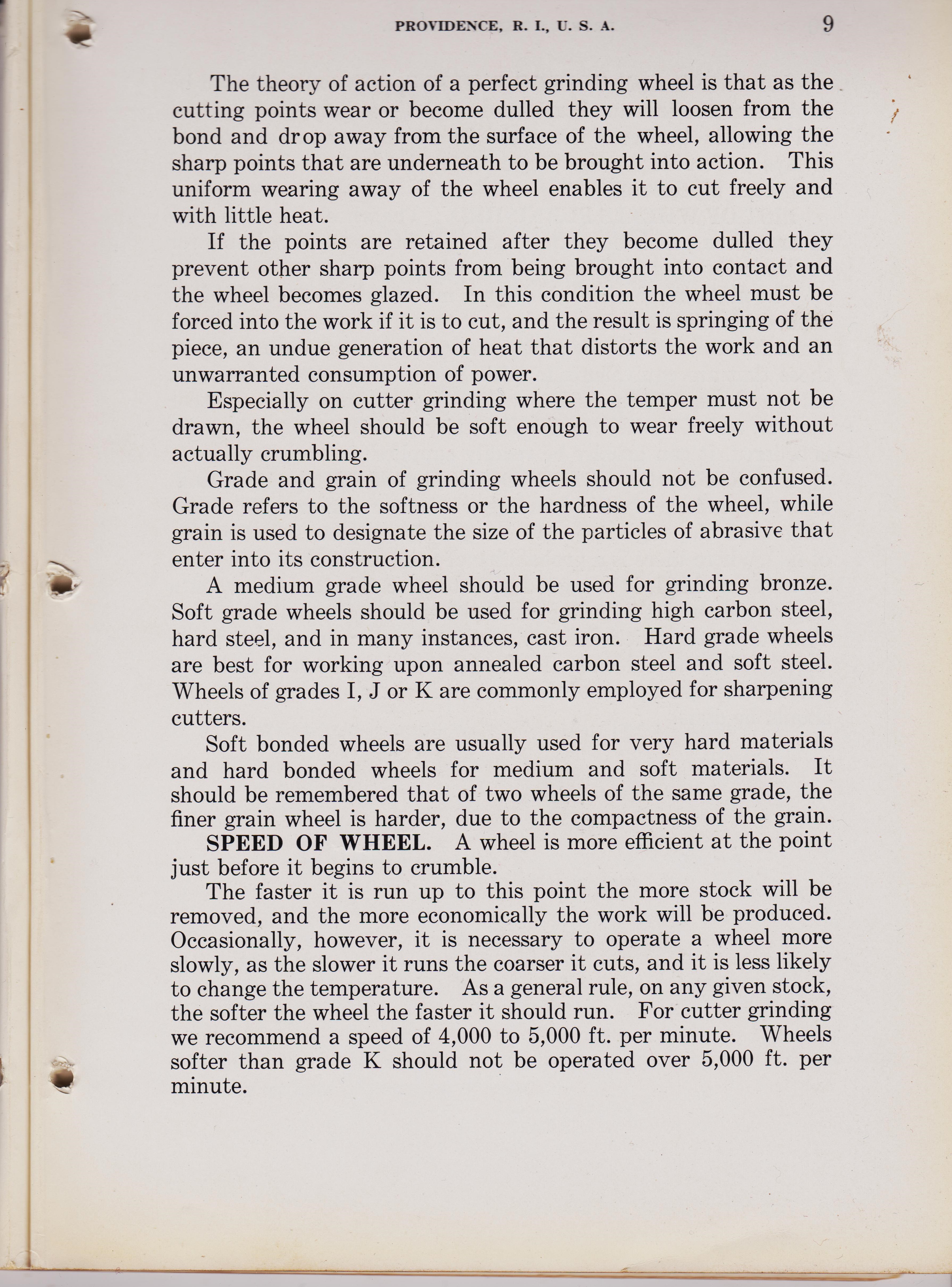
The theory of action of a perfect grinding wheel is that as the cutting points wear or become dulled they will loosen from the bond and drop away from the surface of the wheel, allowing the sharp points that are underneath to be brought into action. This uniform wearing away of the wheel enables it to cut freely and with little heat. If the points are retained after they become dulled they prevent other sharp points from being brought into contact and the wheel becomes glazed. In this condition the wheel must be forced into the work if it is to cut, and the result is springing of the piece, an undue generation of heat that distorts the work and an unwarranted consumption of power. Especially on cutter grinding where the temper must not be drawn, the wheel should be soft enough to wear freely without actually crumbling. Grade and grain of grinding wheels should not be confused. Grade refers to the softness or the hardness of the wheel, while grain is used to designate the size of the particles of abrasive that enter into its construction. A medium grade wheel should be used for grinding bronze. Soft grade wheels should be used for grinding high carbon steel, hard steel, and in many instances, cast iron. Hard grade wheels are best for working upon annealed carbon steel and soft steel. Wheels of grades I, J or K are commonly employed for sharpening cutters. Soft bonded wheels are usually used for very hard materials and hard bonded wheels for medium and soft materials. It should be remembered that of two wheels of the same grade, the finer grain wheel is harder, due to the compactness of the grain.
SPEED OF WHEEL.
A wheel is more efficient at the point just before it begins to crumble. The faster it is run up to this point the more stock will be removed, and the more economically the work will be produced. Occasionally, however, it is necessary to operate a wheel more slowly, as the slower it runs the coarser it cuts, and it is less likely to change the temperature. As a general rule, on any given stock, the softer the wheel the faster it should run. For cutter grinding we recommend a speed of 4,000 to 5,000 ft. per minute. Wheels softer than grade K should not be operated over 5,000 ft. per minute.
%%%%%%%%%%%%%%%%%
page 12
page 9
BROWN & SHARPE MFG. CO.
PROVIDENCE, R. I., U. S. A. page 9
The theory of action of a perfect grinding wheel is that as the cutting points wear or become dulled they will loosen from the bond and drop away from the surface of the wheel, allowing the sharp points that are underneath to be brought into action. This uniform wearing away of the wheel enables it to cut freely and with little heat. If the points are retained after they become dulled they prevent other sharp points from being brought into contact and the wheel becomes glazed. In this condition the wheel must be forced into the work if it is to cut, and the result is springing of the piece, an undue generation of heat that distorts the work and an unwarranted consumption of power. Especially on cutter grinding where the temper must not be drawn, the wheel should be soft enough to wear freely without actually crumbling. Grade and grain of grinding wheels should not be confused. Grade refers to the softness or the hardness of the wheel, while grain is used to designate the size of the particles of abrasive that enter into its construction. A medium grade wheel should be used for grinding bronze. Soft grade wheels should be used for grinding high carbon steel, hard steel, and in many instances, cast iron. Hard grade wheels are best for working upon annealed carbon steel and soft steel. Wheels of grades I, J or K are commonly employed for sharpening cutters. Soft bonded wheels are usually used for very hard materials and hard bonded wheels for medium and soft materials. It should be remembered that of two wheels of the same grade, the finer grain wheel is harder, due to the compactness of the grain.
SPEED OF WHEEL.
A wheel is more efficient at the point just before it begins to crumble. The faster it is run up to this point the more stock will be removed, and the more economically the work will be produced. Occasionally, however, it is necessary to operate a wheel more slowly, as the slower it runs the coarser it cuts, and it is less likely to change the temperature. As a general rule, on any given stock, the softer the wheel the faster it should run. For cutter grinding we recommend a speed of 4,000 to 5,000 ft. per minute. Wheels softer than grade K should not be operated over 5,000 ft. per minute.
How to set up and use the #2 Universal Reamer and Cutter Grinder Machines, B&S Co. printed 1929.
page 10
#2 Universal Cutter Grinder Machine, BROWN & SHARPE MFG. CO.
PROVIDENCE, R. I., U. S. A. page `10
FIG. 898. WOODWARD CUTTER GRINDER. Fig. 89S
is adapted for grinding all kinds of Cutters and Reamers, straight, taper, bevel or spiral. The index centers shown in cut are for grinding cutters without the guide rest or finger against the tooth • such cutters as the Brown & Sharpe Mfg. Co.'s gear cutters, and cutters requiring the face of the tooth to be ground. The index is fitted with a worm gear and worm for fine adjustment in regu-lating the cut, without changing the pawl from the index. Centers swing 6 inches diameter. Price, $90,00; centers, extra, $37.00 ; surface grinding attachment, $50.00. Fig 900 is used for sharpening straight and taper, shell or shank reamers, and for grinding edge and bevel cutters of any angle; straddle and face mills; cotter and hollow mills, and straight or taper milling cutters, cut either straight or spiral, with holes or shanks. It can also be used for sharpening worm and thread tools. Machine takes 18 inches between cell• ters, and takes cutters and shell reamers not exceeding 6 inches in diameter and 7 inches in length. Special circulars, fully descriptive, and prices, upon application
FIG 900. .BROWN & SHARPE UNIVERSAL CUTTER AND REAMER GRINDER.
%%%%%%%%
page 10
#2 Universal Cutter Grinder Machine, BROWN & SHARPE MFG. CO.
PROVIDENCE, R. I., U. S. A. page `10
FIG. 898. WOODWARD CUTTER GRINDER. Fig. 89S
is adapted for grinding all kinds of Cutters and Reamers, straight, taper, bevel or spiral. The index centers shown in cut are for grinding cutters without the guide rest or finger against the tooth • such cutters as the Brown & Sharpe Mfg. Co.'s gear cutters, and cutters requiring the face of the tooth to be ground. The index is fitted with a worm gear and worm for fine adjustment in regu-lating the cut, without changing the pawl from the index. Centers swing 6 inches diameter. Price, $90,00; centers, extra, $37.00 ; surface grinding attachment, $50.00. Fig 900 is used for sharpening straight and taper, shell or shank reamers, and for grinding edge and bevel cutters of any angle; straddle and face mills; cotter and hollow mills, and straight or taper milling cutters, cut either straight or spiral, with holes or shanks. It can also be used for sharpening worm and thread tools. Machine takes 18 inches between cell• ters, and takes cutters and shell reamers not exceeding 6 inches in diameter and 7 inches in length. Special circulars, fully descriptive, and prices, upon application
FIG 900. .BROWN & SHARPE UNIVERSAL CUTTER AND REAMER GRINDER.
%%%%%%%%%
page 13
How to set up and use Universal Cutter Grinder Machines, B&S Co. printed 1929.
page 13
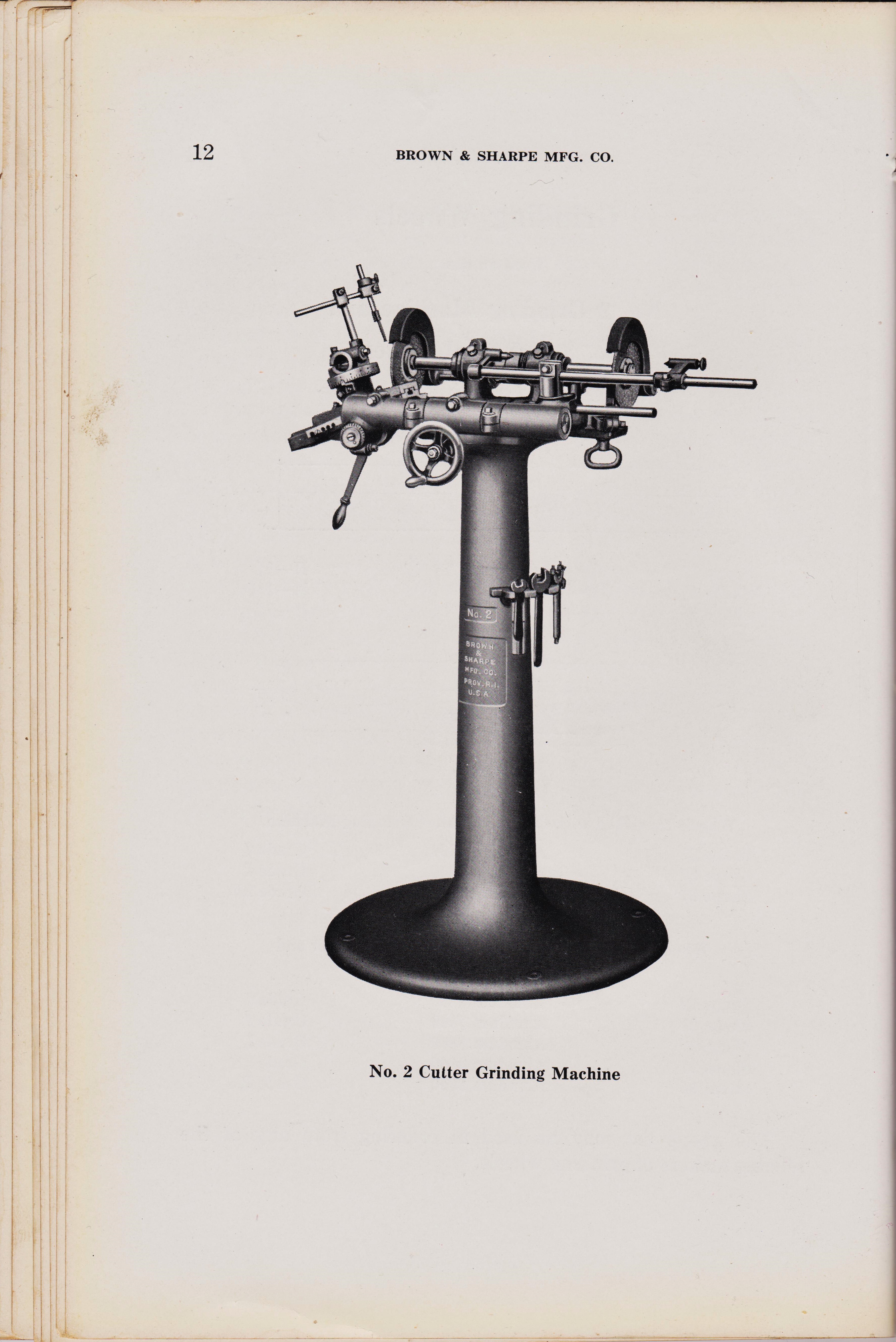
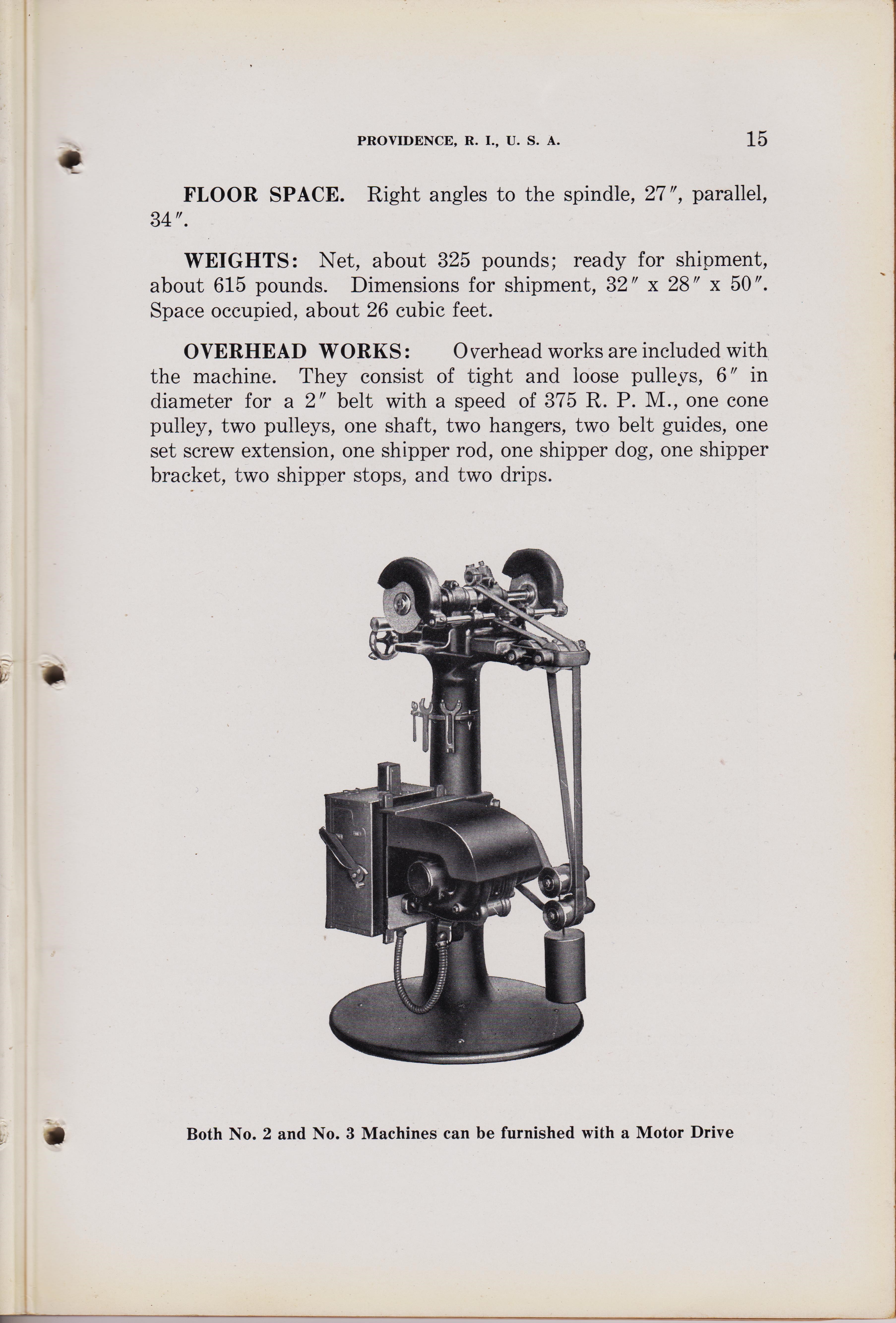
PROVIDENCE, R. I., U. S. A.---NO. 2 CUTTER GRINDING MACHINE
The No. 2 Cutter Grinding Machine
is designed to be compact. It is adaptable to the requirements of the tool room or the shop and because it covers such a small amount of floor space it can be placed among a number of milling machines and not be in the way. Due to its capacity, staunchness, simplicity, and ease of operation, it has proved remarkably adaptable to production work as well as tool room work. It sharpens small shell or shank reamers, straddle or face mills, cutters and hollow mills, bevel cutters of any angle, and straight or taper milling cutters with shanks or holes. It takes 18' between centers and it grinds cutters and shell reamers to 6" in length and 6" in diameter. Thin milling cutters and saws to 24 " in diameter, can also be sharpened. 4 H. P. required to operate the machine at its maximum capacity. BASE: The base is stable and rigid to reduce vibration. It occupies 27" of floor space transversely and 34 " longitudinally with the spindle. The pedestal is 25" in diameter at the floor and the center line of the wheel spindle is 41 " from the floor. SPINDLE HEAD: The spindle head is traversed on accurately scraped ways by a handwheel that turns a screw in a bronze nut in the head. Adjustable gibs provide compensation for wear. The ways are protected from dirt by a shield that completely covers them.
FIG. 5 Section Through Wheel Spindle
WHEEL SPINDLE: The grinding wheel spindle is made of crucible steel and it is hardened, ground and lapped. The ends are accurately tapered to fit wheel sleeves.
%%%%%%% page 14 %%%%%%%%%%
page 13
PROVIDENCE, R. I., U. S. A.---NO. 2 CUTTER GRINDING MACHINE
The No. 2 Cutter Grinding Machine
is designed to be compact. It is adaptable to the requirements of the tool room or the shop and because it covers such a small amount of floor space it can be placed among a number of milling machines and not be in the way. Due to its capacity, staunchness, simplicity, and ease of operation, it has proved remarkably adaptable to production work as well as tool room work. It sharpens small shell or shank reamers, straddle or face mills, cutters and hollow mills, bevel cutters of any angle, and straight or taper milling cutters with shanks or holes. It takes 18' between centers and it grinds cutters and shell reamers to 6" in length and 6" in diameter. Thin milling cutters and saws to 24 " in diameter, can also be sharpened. 4 H. P. required to operate the machine at its maximum capacity. BASE: The base is stable and rigid to reduce vibration. It occupies 27" of floor space transversely and 34 " longitudinally with the spindle. The pedestal is 25" in diameter at the floor and the center line of the wheel spindle is 41 " from the floor. SPINDLE HEAD: The spindle head is traversed on accurately scraped ways by a handwheel that turns a screw in a bronze nut in the head. Adjustable gibs provide compensation for wear. The ways are protected from dirt by a shield that completely covers them.
FIG. 5 Section Through Wheel Spindle
WHEEL SPINDLE: The grinding wheel spindle is made of crucible steel and it is hardened, ground and lapped. The ends are accurately tapered to fit wheel sleeves.
How to set up and use Universal Cutter Grinder Machines, B&S Co. printed 1929.
page 14
#2 Universal Cutter Grinder Machine, BROWN & SHARPE MFG. CO.
PROVIDENCE, R. I., U. S. A. page `14
The spindle bearings are of phosphor bronze. They have adjustment for wear, adequate protection against dust and grit, and are easily lubricated through spring capped oil holes. A two-step pulley for a 1 " belt is attached to the wheel spindle between the bearings. By loosening a safety set screw in the periphery of the larger pulley, the wheel spindle can be adjusted longitudinally 6". The spindle speeds are 2702 and 3375 R. P. M. The wheel guards are adjustable and are substantial enough to give adequate protection to the operator. CUTTER BAR: The cutter bar is of steel, (See Fig. 10, No. 11) hardened, ground, and lapped. It is supported by an arm (See Fig. 10, No. 10), clamped to the main slide bar.
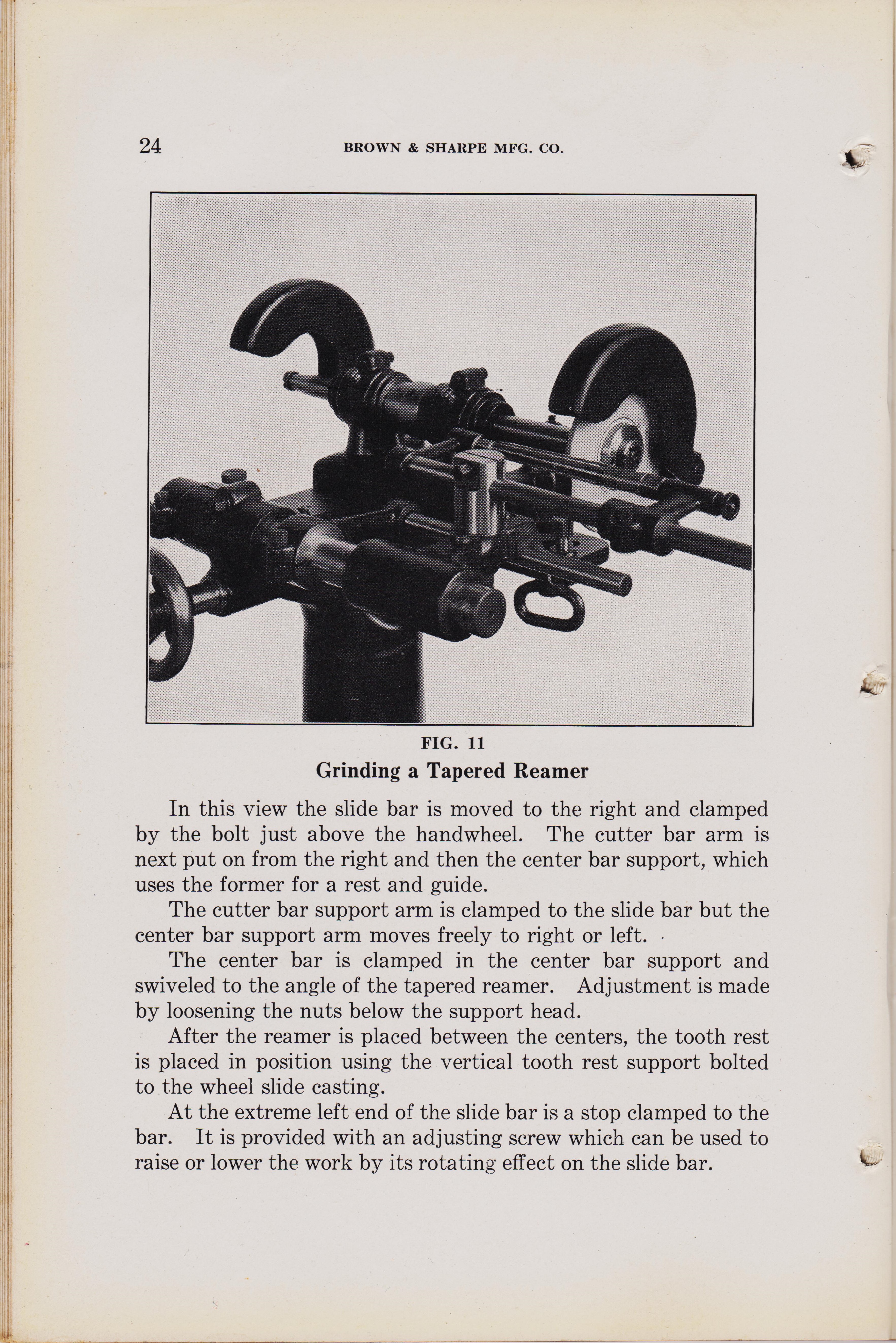
CENTER BAR: The center bar, which carries the footstock and headstock, is carried in the center bar support (See Fig. 11). The centers take 18 " in length.
CENTER BAR SUPPORT HEAD: (See Fig. 10, No. 21.) The center bar support head carries the center bar. It has vertical and angular adjustment for clearance by loosening the screw underneath the head, and it is carried by the support arm that slides on the main bar. When the machine is set up to grind a reamer (See Fig. 11), the shoe of the center support rests on the cutter bar as a guide.
ADJUSTING SCREW: The adjusting screw in the main bar stop is used to obtain clearance. (See Fig. 11, the adjusting screw is in the main bar stop on the extreme left of the main bar). By turning the screw, the main bar and cutter bar clamped to it are raised in the arc of a circle, corresponding to the amount of clearance required.
SLIDING SHELL: The sliding shell is an accessory. It is used to adapt cutters of various sized holes to the *" cutter bar. The sliding shell is provided with step collars that take cutters with i", 1", 1A-", 11", 1/", 1r, 11", and 2 " holes. The cutter is mounted on the sliding shell and collars corresponding to the diameter of its hole; a knurled nut on the end of the shell is tightened and the shell serves as a rigid bushing for the cutter.
TOOL REST: The surface of the tool rest is ground, and when mounted it is square with the wheel. It has vertical and horizontal adjustment with relation to the wheel, and it can be readily mounted on the bracket that is located on the right-hand side of the spindle head.
%%%%%%%%15%%%%%%%%%
page 15
page 14
#2 Universal Cutter Grinder Machine, BROWN & SHARPE MFG. CO.
PROVIDENCE, R. I., U. S. A. page `14
The spindle bearings are of phosphor bronze. They have adjustment for wear, adequate protection against dust and grit, and are easily lubricated through spring capped oil holes. A two-step pulley for a 1 " belt is attached to the wheel spindle between the bearings. By loosening a safety set screw in the periphery of the larger pulley, the wheel spindle can be adjusted longitudinally 6". The spindle speeds are 2702 and 3375 R. P. M. The wheel guards are adjustable and are substantial enough to give adequate protection to the operator. CUTTER BAR: The cutter bar is of steel, (See Fig. 10, No. 11) hardened, ground, and lapped. It is supported by an arm (See Fig. 10, No. 10), clamped to the main slide bar.
CENTER BAR: The center bar, which carries the footstock and headstock, is carried in the center bar support (See Fig. 11). The centers take 18 " in length.
CENTER BAR SUPPORT HEAD: (See Fig. 10, No. 21.) The center bar support head carries the center bar. It has vertical and angular adjustment for clearance by loosening the screw underneath the head, and it is carried by the support arm that slides on the main bar. When the machine is set up to grind a reamer (See Fig. 11), the shoe of the center support rests on the cutter bar as a guide.
ADJUSTING SCREW: The adjusting screw in the main bar stop is used to obtain clearance. (See Fig. 11, the adjusting screw is in the main bar stop on the extreme left of the main bar). By turning the screw, the main bar and cutter bar clamped to it are raised in the arc of a circle, corresponding to the amount of clearance required.
SLIDING SHELL: The sliding shell is an accessory. It is used to adapt cutters of various sized holes to the *" cutter bar. The sliding shell is provided with step collars that take cutters with i", 1", 1A-", 11", 1/", 1r, 11", and 2 " holes. The cutter is mounted on the sliding shell and collars corresponding to the diameter of its hole; a knurled nut on the end of the shell is tightened and the shell serves as a rigid bushing for the cutter.
TOOL REST: The surface of the tool rest is ground, and when mounted it is square with the wheel. It has vertical and horizontal adjustment with relation to the wheel, and it can be readily mounted on the bracket that is located on the right-hand side of the spindle head.
How to set up and use Universal Cutter Grinder Machines, B&S Co. printed 1929.
page 15
#2 Universal Cutter Grinder Machine, BROWN & SHARPE MFG. CO.
PROVIDENCE, R. I., U. S. A. page `15
"
width="900" height="1200"
alt="https://antiquemachinery.com/images-2020/Universal-Cutter-and-Reamer-Grinder-Machine-Brown-and-Sharpe-Mfg-Co-1929-No2-No3-pg-14.jpeg">
page 15
#2 Universal Cutter Grinder Machine, BROWN & SHARPE MFG. CO.
PROVIDENCE, R. I., U. S. A. page `15
How to set up and use Universal Cutter Grinder Machines, B&S Co. printed 1929.
page 15
#2 Universal Cutter Grinder Machine, BROWN & SHARPE MFG. CO.
PROVIDENCE, R. I., U. S. A. page `15
%%%%%%%16%%%%%%%%%%
page 16
page 15
#2 Universal Cutter Grinder Machine, BROWN & SHARPE MFG. CO.
PROVIDENCE, R. I., U. S. A. page `15
How to set up and use Universal Cutter Grinder Machines, B&S Co. printed 1929.
page 16
#2 Universal Cutter Grinder Machine, BROWN & SHARPE MFG. CO.
PROVIDENCE, R. I., U. S. A. page `16
"
width="900" height="1200"
alt="https://antiquemachinery.com/images-2020/Universal-Cutter-and-Reamer-Grinder-Machine-Brown-and-Sharpe-Mfg-Co-1929-No2-No3-pg-14.jpeg">
page 16
#2 Universal Cutter Grinder Machine, BROWN & SHARPE MFG. CO.
PROVIDENCE, R. I., U. S. A. page `16
How to set up and use Universal Cutter Grinder Machines, B&S Co. printed 1929.
page 16
#2 Universal Cutter Grinder Machine, BROWN & SHARPE MFG. CO.
PROVIDENCE, R. I., U. S. A. page `15
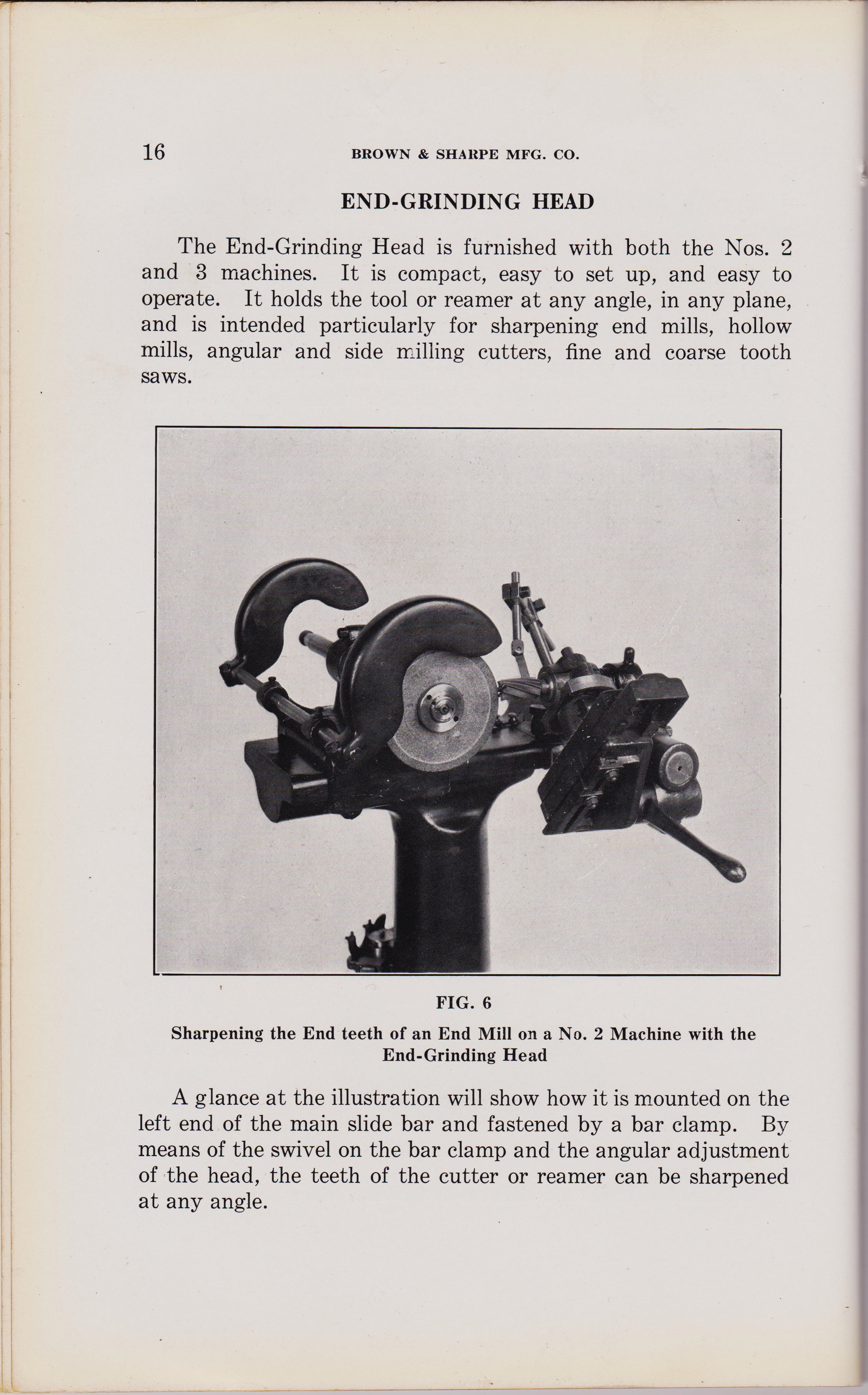
END-GRINDING HEAD
The End-Grinding Head is furnished with both the Nos. 2 and 3 machines. It is compact, easy to set up, and easy to operate. It holds the tool or reamer at any angle, in any plane, and is intended particularly for sharpening end mills, hollow mills, angular and side milling cutters, fine and coarse tooth saws.
FIG. 6
Sharpening the End teeth of an End Mill on a No. 2 Machine with the End-Grinding Head
A glance at the illustration will show how it is mounted on the left end of the main slide bar and fastened by a bar clamp. By means of the swivel on the bar clamp and the angular adjustment of the head, the teeth of the cutter or reamer can be sharpened at any angle.
%%%%%%%%%%%%%%%%%
page 17
page 16
#2 Universal Cutter Grinder Machine, BROWN & SHARPE MFG. CO.
PROVIDENCE, R. I., U. S. A. page `15
END-GRINDING HEAD
The End-Grinding Head is furnished with both the Nos. 2 and 3 machines. It is compact, easy to set up, and easy to operate. It holds the tool or reamer at any angle, in any plane, and is intended particularly for sharpening end mills, hollow mills, angular and side milling cutters, fine and coarse tooth saws.
FIG. 6
Sharpening the End teeth of an End Mill on a No. 2 Machine with the End-Grinding Head
A glance at the illustration will show how it is mounted on the left end of the main slide bar and fastened by a bar clamp. By means of the swivel on the bar clamp and the angular adjustment of the head, the teeth of the cutter or reamer can be sharpened at any angle.
How to set up and use Universal Cutter Grinder Machines, B&S Co. printed 1929.
page 17
#2 Universal Cutter Grinder Machine, BROWN & SHARPE MFG. CO.
PROVIDENCE, R. I., U. S. A. page `15
END-GRINDING HEAD
The End-Grinding Head is furnished with both the Nos. 2 and 3 machines. It is compact, easy to set up, and easy to operate. It holds the tool or reamer at any angle, in any plane, and is intended particularly for sharpening end mills, hollow mills, angular and side milling cutters, fine and coarse tooth saws.
FIG. 6
Sharpening the End teeth of an End Mill on a No. 2 Machine with the End-Grinding Head
A glance at the illustration will show how it is mounted on the left end of the main slide bar and fastened by a bar clamp. By means of the swivel on the bar clamp and the angular adjustment of the head, the teeth of the cutter or reamer can be sharpened at any angle.
%%%%%%%%%%%%%%%%%
page 18
page 17
#2 Universal Cutter Grinder Machine, BROWN & SHARPE MFG. CO.
PROVIDENCE, R. I., U. S. A. page `15
END-GRINDING HEAD
The End-Grinding Head is furnished with both the Nos. 2 and 3 machines. It is compact, easy to set up, and easy to operate. It holds the tool or reamer at any angle, in any plane, and is intended particularly for sharpening end mills, hollow mills, angular and side milling cutters, fine and coarse tooth saws.
FIG. 6
Sharpening the End teeth of an End Mill on a No. 2 Machine with the End-Grinding Head
A glance at the illustration will show how it is mounted on the left end of the main slide bar and fastened by a bar clamp. By means of the swivel on the bar clamp and the angular adjustment of the head, the teeth of the cutter or reamer can be sharpened at any angle.
How to set up and use Universal Cutter Grinder Machines, B&S Co. printed 1929.
page 18
#2 Universal Cutter Grinder Machine, BROWN & SHARPE MFG. CO.
PROVIDENCE, R. I., U. S. A. page `18
"
width="900" height="1200"
alt="https://antiquemachinery.com/images-2020/Universal-Cutter-and-Reamer-Grinder-Machine-Brown-and-Sharpe-Mfg-Co-1929-No2-No3-pg-14.jpeg">
page 18
#2 Universal Cutter Grinder Machine, BROWN & SHARPE MFG. CO.
PROVIDENCE, R. I., U. S. A. page `18
How to set up and use Universal Cutter Grinder Machines, B&S Co. printed 1929.
page 18
#2 Universal Cutter Grinder Machine, BROWN & SHARPE MFG. CO.
page 18 BROWN & SHARPE MFG. CO.
FORMED CUTTER GRINDING ATTACHMENT
The Formed Cutter Grinding Attachment shown in the accompanying illustration, can be used on both the Nos. 2 and 3 Machines. Straight gashed hobs as well as formed cutters can be ground radially on this attachment. It is not a part of the regular eauipment of the machine, but is supplied at an additional charge. The attachment is bolted at its upper end to the main slide bar and at the lower end it is clamped to the column.
FIG. 8 Sharpening a Formed Cutter (HOB) on a No. 2
Machine with the Formed Cutter Grinding Attachment The slide is actuated by a handwheel that turns a pinion meshing with a rack under the slide. The motion is limited by an adjustable stop on the front side. The slide can be clamped in place by the binding knob at the upper end. Standard Brown & Sharpe 41" Index Centers are adjustable along a T Slot in the slide and can be clamped by the special nuts with a pin wrench.
%%%%%%%%19%%%%%%%%%
page 19
page 18
#2 Universal Cutter Grinder Machine, BROWN & SHARPE MFG. CO.
page 18 BROWN & SHARPE MFG. CO.
FORMED CUTTER GRINDING ATTACHMENT
The Formed Cutter Grinding Attachment shown in the accompanying illustration, can be used on both the Nos. 2 and 3 Machines. Straight gashed hobs as well as formed cutters can be ground radially on this attachment. It is not a part of the regular eauipment of the machine, but is supplied at an additional charge. The attachment is bolted at its upper end to the main slide bar and at the lower end it is clamped to the column.
FIG. 8 Sharpening a Formed Cutter (HOB) on a No. 2
Machine with the Formed Cutter Grinding Attachment The slide is actuated by a handwheel that turns a pinion meshing with a rack under the slide. The motion is limited by an adjustable stop on the front side. The slide can be clamped in place by the binding knob at the upper end. Standard Brown & Sharpe 41" Index Centers are adjustable along a T Slot in the slide and can be clamped by the special nuts with a pin wrench.
How to set up and use Universal Cutter Grinder Machines, B&S Co. printed 1929.
page 19
#2 Universal Cutter Grinder Machine, BROWN & SHARPE MFG. CO.
PROVIDENCE, R. I., U. S. A. page `19
The head stock is provided with an indexing worm and worm wheel. The plate has 24 holes and by disengaging the worm, it can be turned by hand. The centers swing 44" in diameter and take 10r in length, and by the use of raising blocks, cutters to 8" in diameter can be ground. By moving the wheel slide backward or forward the diameter of the work between the centers can be accommodated. Side adjustment can be made by adjusting the wheel spindle or by moving the slide bar to which the attachment is rigidly clamped, to the right or left. WEIGHTS: Net, about 76 pounds; ready for shipment, about 104 pounds. Dimensions for shipment, 22" x 14" x 12"; space occupied, about 2 cubic feet.
FIG. 9
Sharpening a Hob on a No. 3 Machine with the Formed Cutter Grinding Attachment
%%%%%%%%20%%%%%%%%%
page 19
#2 Universal Cutter Grinder Machine, BROWN & SHARPE MFG. CO.
PROVIDENCE, R. I., U. S. A. page `19
The head stock is provided with an indexing worm and worm wheel. The plate has 24 holes and by disengaging the worm, it can be turned by hand. The centers swing 44" in diameter and take 10r in length, and by the use of raising blocks, cutters to 8" in diameter can be ground. By moving the wheel slide backward or forward the diameter of the work between the centers can be accommodated. Side adjustment can be made by adjusting the wheel spindle or by moving the slide bar to which the attachment is rigidly clamped, to the right or left. WEIGHTS: Net, about 76 pounds; ready for shipment, about 104 pounds. Dimensions for shipment, 22" x 14" x 12"; space occupied, about 2 cubic feet.
FIG. 9
Sharpening a Hob on a No. 3 Machine with the Formed Cutter Grinding Attachment
How to set up and use Universal Cutter Grinder Machines, B&S Co. printed 1929.
page 20
#2 Universal Cutter Grinder Machine, BROWN & SHARPE MFG. CO.
PROVIDENCE, R. I., U. S. A. page `20
"
width="900" height="1250"
page 20
#2 Universal Cutter Grinder Machine, BROWN & SHARPE MFG. CO.
PROVIDENCE, R. I., U. S. A. page `20
How to set up and use Universal Cutter Grinder Machines, B&S Co. printed 1929.
page 21
#2 Universal Cutter Grinder Machine, BROWN & SHARPE MFG. CO.
PROVIDENCE, R. I., U. S. A. page `21
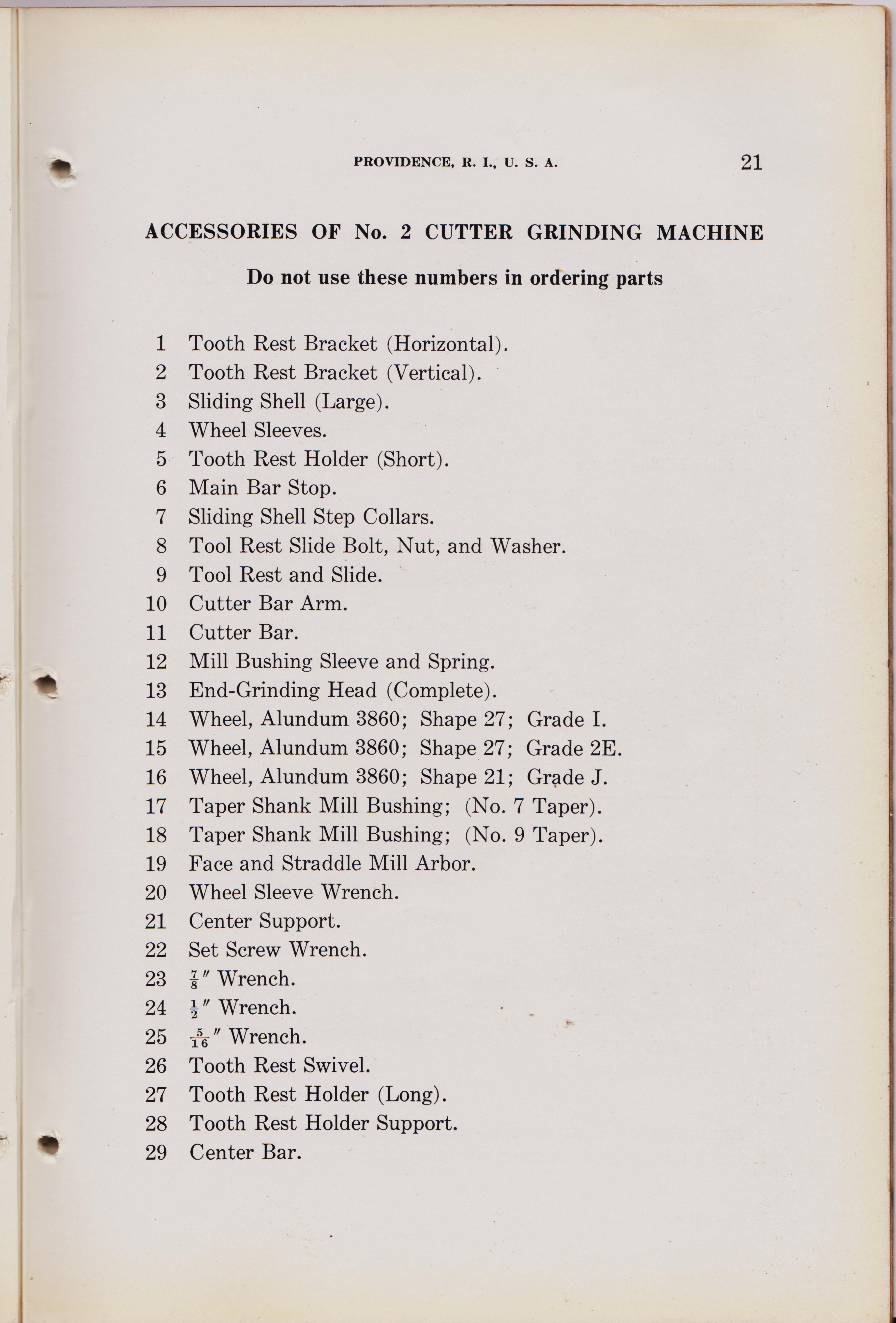
ACCESSORIES OF No. 2 CUTTER GRINDING MACHINE Do not use these numbers in ordering parts
1 Tooth Rest Bracket (Horizontal).
PROVIDENCE, R. I., U. S. A. 19 The head stock is provided with an indexing worm and worm wheel. The plate has 24 holes and by disengaging the worm, it can be turned by hand. The centers swing 44" in diameter and take 10r in length, and by the use of raising blocks, cutters to 8" in diameter can be ground. By moving the wheel slide backward or forward the diameter of the work between the centers can be accommodated. Side adjustment can be made by adjusting the wheel spindle or by moving the slide bar to which the attachment is rigidly clamped, to the right or left. WEIGHTS: Net, about 76 pounds; ready for shipment, about 104 pounds. Dimensions for shipment, 22" x 14" x 12"; space occupied, about 2 cubic feet. FIG. 9 Sharpening a Hob on a No. 3 Machine with the Formed Cutter Grinding Attachment 1 Tooth Rest Bracket (Horizontal).------------------------------ 2 Tooth Rest Bracket (Vertical).
3 Sliding Shell (Large).--------------------------------------------4 Wheel Sleeves.
4 Wheel Sleeves. --------------------------------------------------5 Tooth Rest Holder (Short).
6 Main Bar Stop.--------------------------------------------------- 7 Sliding Shell Step Collars.
8 Tool Rest Slide Bolt, Nut, and Washer. -----------------------9 Tool Rest and Slide.
10 Cutter Bar Arm. 11 Cutter Bar.
12 Mill Bushing Sleeve and Spring.
13 End-Grinding Head (Complete).
14 Wheel, Alundum 3860; Shape 27; Grade I.
15 Wheel, Alundum 3860; Shape 27; Grade 2E.
16 Wheel, Alundum 3860; Shape 21; Grade J.
17 Taper Shank Mill Bushing; (No. 7 Taper).
18 Taper Shank Mill Bushing; (No. 9 Taper).
19 Face and Straddle Mill Arbor.
20 Wheel Sleeve Wrench.
21 Center Support.
22 Set Screw Wrench.
23 i" Wrench.
24 2" Wrench.
25 26" Wrench.
26 Tooth Rest Swivel.
27 Tooth Rest Holder (Long).
28 Tooth Rest Holder Support.
29 Center Bar.
.
%%%%%%%%%21%%%%%%%
page 21
#2 Universal Cutter Grinder Machine, BROWN & SHARPE MFG. CO.
PROVIDENCE, R. I., U. S. A. page `21
ACCESSORIES OF No. 2 CUTTER GRINDING MACHINE Do not use these numbers in ordering parts
1 Tooth Rest Bracket (Horizontal).
PROVIDENCE, R. I., U. S. A. 19 The head stock is provided with an indexing worm and worm wheel. The plate has 24 holes and by disengaging the worm, it can be turned by hand. The centers swing 44" in diameter and take 10r in length, and by the use of raising blocks, cutters to 8" in diameter can be ground. By moving the wheel slide backward or forward the diameter of the work between the centers can be accommodated. Side adjustment can be made by adjusting the wheel spindle or by moving the slide bar to which the attachment is rigidly clamped, to the right or left. WEIGHTS: Net, about 76 pounds; ready for shipment, about 104 pounds. Dimensions for shipment, 22" x 14" x 12"; space occupied, about 2 cubic feet. FIG. 9 Sharpening a Hob on a No. 3 Machine with the Formed Cutter Grinding Attachment 1 Tooth Rest Bracket (Horizontal).------------------------------ 2 Tooth Rest Bracket (Vertical).
3 Sliding Shell (Large).--------------------------------------------4 Wheel Sleeves.
4 Wheel Sleeves. --------------------------------------------------5 Tooth Rest Holder (Short).
6 Main Bar Stop.--------------------------------------------------- 7 Sliding Shell Step Collars.
8 Tool Rest Slide Bolt, Nut, and Washer. -----------------------9 Tool Rest and Slide.
10 Cutter Bar Arm. 11 Cutter Bar.
12 Mill Bushing Sleeve and Spring.
13 End-Grinding Head (Complete).
14 Wheel, Alundum 3860; Shape 27; Grade I.
15 Wheel, Alundum 3860; Shape 27; Grade 2E.
16 Wheel, Alundum 3860; Shape 21; Grade J.
17 Taper Shank Mill Bushing; (No. 7 Taper).
18 Taper Shank Mill Bushing; (No. 9 Taper).
19 Face and Straddle Mill Arbor.
20 Wheel Sleeve Wrench.
21 Center Support.
22 Set Screw Wrench.
23 i" Wrench.
24 2" Wrench.
25 26" Wrench.
26 Tooth Rest Swivel.
27 Tooth Rest Holder (Long).
28 Tooth Rest Holder Support.
29 Center Bar.
.
How to set up and use Universal Cutter Grinder Machines, B&S Co. printed 1929.
page 23
#2 Universal Cutter Grinder Machine, BROWN & SHARPE MFG. CO.
PROVIDENCE, R. I., U. S. A. page `20
"
width="900" height="1250"
page 23
#2 Universal Cutter Grinder Machine, BROWN & SHARPE MFG. CO.
PROVIDENCE, R. I., U. S. A. page `20
How to set up and use Universal Cutter Grinder Machines, B&S Co. printed 1929.
page 20
#2 Universal Cutter Grinder Machine, BROWN & SHARPE MFG. CO.
PROVIDENCE, R. I., U. S. A. page `20
END-GRINDING HEAD
The End-Grinding Head is furnished with both the Nos. 2 and 3 machines. It is compact, easy to set up, and easy to operate. It holds the tool or reamer at any angle, in any plane, and is intended particularly for sharpening end mills, hollow mills, angular and side milling cutters, fine and coarse tooth saws.
FIG. 6
Sharpening the End teeth of an End Mill on a No. 2 Machine with the End-Grinding Head
A glance at the illustration will show how it is mounted on the left end of the main slide bar and fastened by a bar clamp. By means of the swivel on the bar clamp and the angular adjustment of the head, the teeth of the cutter or reamer can be sharpened at any angle.
%%%%%%%%%22%%%%%%%%
page 20
#2 Universal Cutter Grinder Machine, BROWN & SHARPE MFG. CO.
PROVIDENCE, R. I., U. S. A. page `20
END-GRINDING HEAD
The End-Grinding Head is furnished with both the Nos. 2 and 3 machines. It is compact, easy to set up, and easy to operate. It holds the tool or reamer at any angle, in any plane, and is intended particularly for sharpening end mills, hollow mills, angular and side milling cutters, fine and coarse tooth saws.
FIG. 6
Sharpening the End teeth of an End Mill on a No. 2 Machine with the End-Grinding Head
A glance at the illustration will show how it is mounted on the left end of the main slide bar and fastened by a bar clamp. By means of the swivel on the bar clamp and the angular adjustment of the head, the teeth of the cutter or reamer can be sharpened at any angle.
How to set up and use Universal Cutter Grinder Machines, B&S Co. printed 1929.
page 23
#2 Universal Cutter Grinder Machine, BROWN & SHARPE MFG. CO.
PROVIDENCE, R. I., U. S. A. page `20
"
width="900" height="1250"
page 23
#2 Universal Cutter Grinder Machine, BROWN & SHARPE MFG. CO.
PROVIDENCE, R. I., U. S. A. page `20
How to set up and use Universal Cutter Grinder Machines, B&S Co. printed 1929.
page 20
#2 Universal Cutter Grinder Machine, BROWN & SHARPE MFG. CO.
PROVIDENCE, R. I., U. S. A. page `20
END-GRINDING HEAD
The End-Grinding Head is furnished with both the Nos. 2 and 3 machines. It is compact, easy to set up, and easy to operate. It holds the tool or reamer at any angle, in any plane, and is intended particularly for sharpening end mills, hollow mills, angular and side milling cutters, fine and coarse tooth saws.
FIG. 6
Sharpening the End teeth of an End Mill on a No. 2 Machine with the End-Grinding Head
A glance at the illustration will show how it is mounted on the left end of the main slide bar and fastened by a bar clamp. By means of the swivel on the bar clamp and the angular adjustment of the head, the teeth of the cutter or reamer can be sharpened at any angle.
%%%%%%%%%24%%%%%%%%
page 20
#2 Universal Cutter Grinder Machine, BROWN & SHARPE MFG. CO.
PROVIDENCE, R. I., U. S. A. page `20
END-GRINDING HEAD
The End-Grinding Head is furnished with both the Nos. 2 and 3 machines. It is compact, easy to set up, and easy to operate. It holds the tool or reamer at any angle, in any plane, and is intended particularly for sharpening end mills, hollow mills, angular and side milling cutters, fine and coarse tooth saws.
FIG. 6
Sharpening the End teeth of an End Mill on a No. 2 Machine with the End-Grinding Head
A glance at the illustration will show how it is mounted on the left end of the main slide bar and fastened by a bar clamp. By means of the swivel on the bar clamp and the angular adjustment of the head, the teeth of the cutter or reamer can be sharpened at any angle.
How to set up and use Universal Cutter Grinder Machines, B&S Co. printed 1929.
page 24 fix
#2 Universal Cutter Grinder Machine, BROWN & SHARPE MFG. CO.
PROVIDENCE, R. I., U. S. A. page `20
"
width="900" height="1250"
page 24 fix
#2 Universal Cutter Grinder Machine, BROWN & SHARPE MFG. CO.
PROVIDENCE, R. I., U. S. A. page `20
How to set up and use Universal Cutter Grinder Machines, B&S Co. printed 1929.
page 24
#2 Universal Cutter Grinder Machine, BROWN & SHARPE MFG. CO.
PROVIDENCE, R. I., U. S. A. page `20
END-GRINDING HEAD
The End-Grinding Head is furnished with both the Nos. 2 and 3 machines. It is compact, easy to set up, and easy to operate. It holds the tool or reamer at any angle, in any plane, and is intended particularly for sharpening end mills, hollow mills, angular and side milling cutters, fine and coarse tooth saws.
FIG. 6
Sharpening the End teeth of an End Mill on a No. 2 Machine with the End-Grinding Head
A glance at the illustration will show how it is mounted on the left end of the main slide bar and fastened by a bar clamp. By means of the swivel on the bar clamp and the angular adjustment of the head, the teeth of the cutter or reamer can be sharpened at any angle.
%%%%%%%%%25%%%%%%%%
page 24
#2 Universal Cutter Grinder Machine, BROWN & SHARPE MFG. CO.
PROVIDENCE, R. I., U. S. A. page `20
END-GRINDING HEAD
The End-Grinding Head is furnished with both the Nos. 2 and 3 machines. It is compact, easy to set up, and easy to operate. It holds the tool or reamer at any angle, in any plane, and is intended particularly for sharpening end mills, hollow mills, angular and side milling cutters, fine and coarse tooth saws.
FIG. 6
Sharpening the End teeth of an End Mill on a No. 2 Machine with the End-Grinding Head
A glance at the illustration will show how it is mounted on the left end of the main slide bar and fastened by a bar clamp. By means of the swivel on the bar clamp and the angular adjustment of the head, the teeth of the cutter or reamer can be sharpened at any angle.
How to set up and use Universal Cutter Grinder Machines, B&S Co. printed 1929.
page 25
#2 Universal Cutter Grinder Machine, BROWN & SHARPE MFG. CO.
PROVIDENCE, R. I., U. S. A. page `20
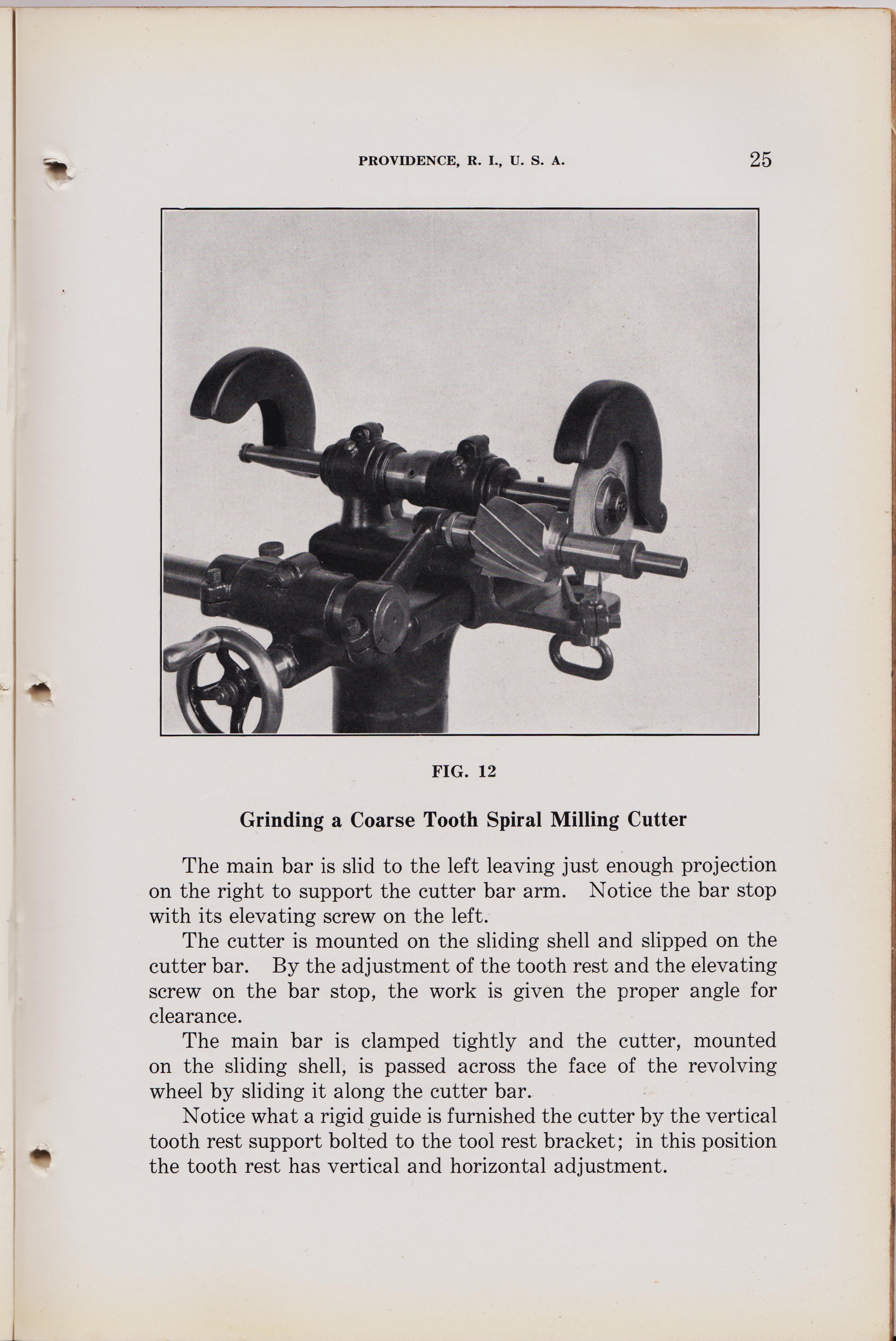
FIG. 12
Grinding a Coarse Tooth Spiral Milling Cutter
The main bar is slid to the left leaving just enough projection on the right to support the cutter bar arm. Notice the bar stop with its elevating screw on the left. The cutter is mounted on the sliding shell and slipped on the cutter bar. By the adjustment of the tooth rest and the elevating screw on the bar stop, the work is given the proper angle for clearance. The main bar is clamped tightly and the cutter, mounted on the sliding shell, is passed across the face of the revolving wheel by sliding it along the cutter bar. Notice what a rigid guide is furnished the cutter by the vertical tooth rest support bolted to the tool rest bracket; in this position the tooth rest has vertical and horizontal adjustment.
"
width="900" height="1250"
page 25
#2 Universal Cutter Grinder Machine, BROWN & SHARPE MFG. CO.
PROVIDENCE, R. I., U. S. A. page `20
FIG. 12
Grinding a Coarse Tooth Spiral Milling Cutter
The main bar is slid to the left leaving just enough projection on the right to support the cutter bar arm. Notice the bar stop with its elevating screw on the left. The cutter is mounted on the sliding shell and slipped on the cutter bar. By the adjustment of the tooth rest and the elevating screw on the bar stop, the work is given the proper angle for clearance. The main bar is clamped tightly and the cutter, mounted on the sliding shell, is passed across the face of the revolving wheel by sliding it along the cutter bar. Notice what a rigid guide is furnished the cutter by the vertical tooth rest support bolted to the tool rest bracket; in this position the tooth rest has vertical and horizontal adjustment.
How to set up and use Universal Cutter Grinder Machines, B&S Co. printed 1929.
page 25 fix
#2 Universal Cutter Grinder Machine, BROWN & SHARPE MFG. CO.
PROVIDENCE, R. I., U. S. A. page `20
END-GRINDING HEAD
21 ACCESSORIES OF No. 2 CUTTER GRINDING MACHINE Do not use these numbers in ordering parts 1 Tooth Rest Bracket (Horizontal). 2 Tooth Rest Bracket (Vertical). 3 Sliding Shell (Large). 4 Wheel Sleeves. 5 Tooth Rest Holder (Short). 6 Main Bar Stop. 7 Sliding Shell Step Collars. 8 Tool Rest Slide Bolt, Nut, and Washer. 9 Tool Rest and Slide. 10 Cutter Bar Arm. 11 Cutter Bar. 12 Mill Bushing Sleeve and Spring. 13 End-Grinding Head (Complete). 14 Wheel, Alundum 3860; Shape 27; Grade I. 15 Wheel, Alundum 3860; Shape 27; Grade 2E. 16 Wheel, Alundum 3860; Shape 21; Grade J. 17 Taper Shank Mill Bushing; (No. 7 Taper). 18 Taper Shank Mill Bushing; (No. 9 Taper). 19 Face and Straddle Mill Arbor. 20 Wheel Sleeve Wrench. 21 Center Support. 22 Set Screw Wrench. 23 i" Wrench. 24 2" Wrench. 25 26" Wrench. 26 Tooth Rest Swivel. 27 Tooth Rest Holder (Long). 28 Tooth Rest Holder Support. 29 Center Bar.
%%%%%%%%%26%%%%%%%%
page 25 fix
#2 Universal Cutter Grinder Machine, BROWN & SHARPE MFG. CO.
PROVIDENCE, R. I., U. S. A. page `20
END-GRINDING HEAD
21 ACCESSORIES OF No. 2 CUTTER GRINDING MACHINE Do not use these numbers in ordering parts 1 Tooth Rest Bracket (Horizontal). 2 Tooth Rest Bracket (Vertical). 3 Sliding Shell (Large). 4 Wheel Sleeves. 5 Tooth Rest Holder (Short). 6 Main Bar Stop. 7 Sliding Shell Step Collars. 8 Tool Rest Slide Bolt, Nut, and Washer. 9 Tool Rest and Slide. 10 Cutter Bar Arm. 11 Cutter Bar. 12 Mill Bushing Sleeve and Spring. 13 End-Grinding Head (Complete). 14 Wheel, Alundum 3860; Shape 27; Grade I. 15 Wheel, Alundum 3860; Shape 27; Grade 2E. 16 Wheel, Alundum 3860; Shape 21; Grade J. 17 Taper Shank Mill Bushing; (No. 7 Taper). 18 Taper Shank Mill Bushing; (No. 9 Taper). 19 Face and Straddle Mill Arbor. 20 Wheel Sleeve Wrench. 21 Center Support. 22 Set Screw Wrench. 23 i" Wrench. 24 2" Wrench. 25 26" Wrench. 26 Tooth Rest Swivel. 27 Tooth Rest Holder (Long). 28 Tooth Rest Holder Support. 29 Center Bar.
How to set up and use the #2 Universal Cutter Grinder Machines, B&S Co. printed 1929.
page 26
#2 Universal Cutter Grinder Machine, BROWN & SHARPE MFG. CO.
PROVIDENCE, R. I., U. S. A. page `26
"
width="900" height="1250"
page 26
#2 Universal Cutter Grinder Machine, BROWN & SHARPE MFG. CO.
PROVIDENCE, R. I., U. S. A. page `26
How to set up and use Universal Cutter Grinder Machines, B&S Co. printed 1929.
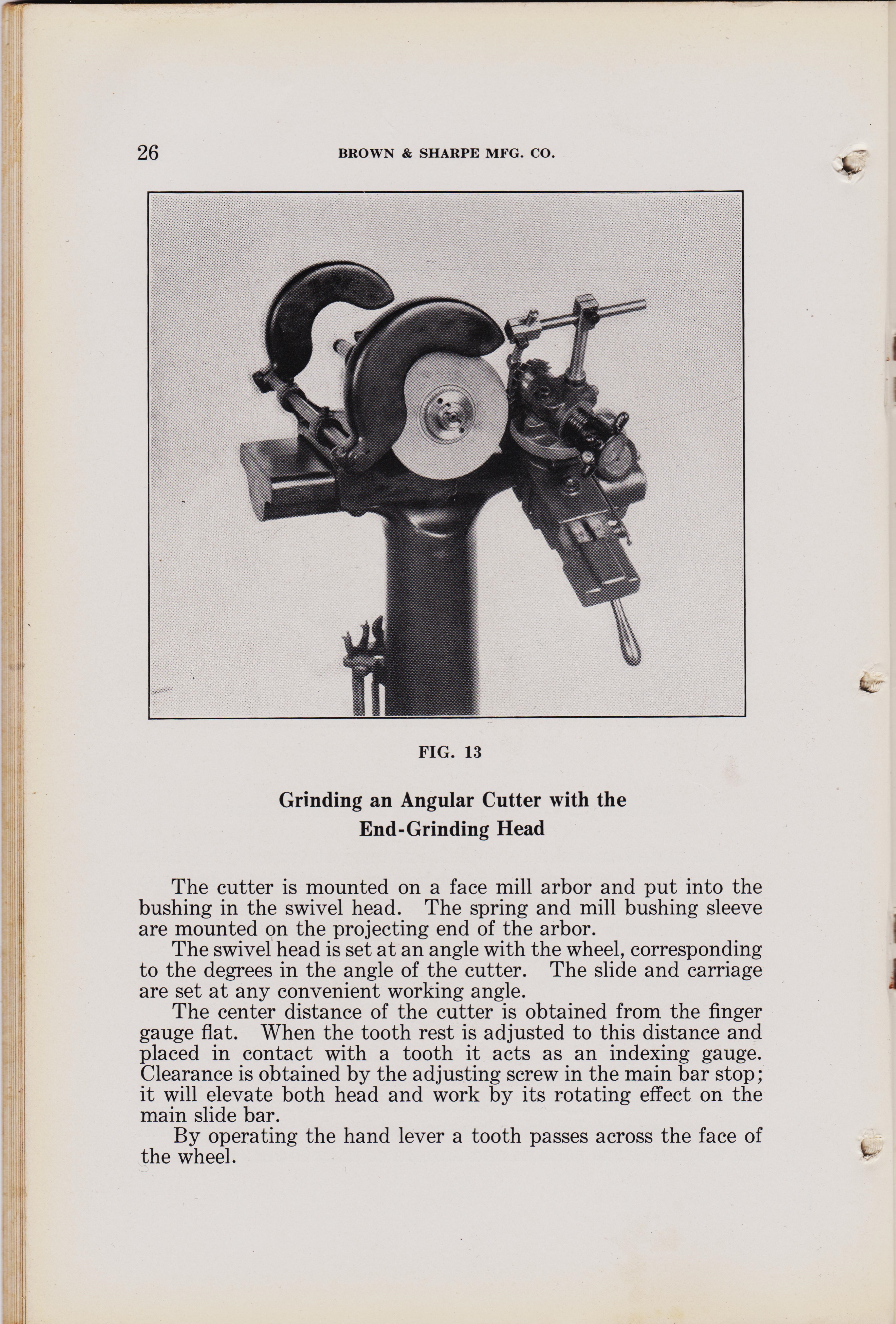
page 26 Grinding an Angular Cutter with the End-Grinding Head
#2 Universal Cutter Grinder Machine, BROWN & SHARPE MFG. CO. PROVIDENCE, R. I., U. S. A.
page 26. END-GRINDING HEAD
26 BROWN & SHARPE MFG. CO. FIG. 13 Grinding an Angular Cutter with the End-Grinding Head The cutter is mounted on a face mill arbor and put into the bushing in the swivel head. The spring and mill bushing sleeve are mounted on the projecting end of the arbor. The swivel head is set at an angle with the wheel, corresponding to the degrees in the angle of the cutter. The slide and carriage are set at any convenient working angle. The center distance of the cutter is obtained from the finger gauge flat. When the tooth rest is adjusted to this distance and placed in contact with a tooth it acts as an indexing gauge. Clearance is obtained by the adjusting screw in the main bar stop; it will elevate both head and work by its rotating effect on the main slide bar. By operating the hand lever a tooth passes across the face of the wheel.
%%%%%%%%%27%%%%%%%%
page 26 Grinding an Angular Cutter with the End-Grinding Head
#2 Universal Cutter Grinder Machine, BROWN & SHARPE MFG. CO. PROVIDENCE, R. I., U. S. A.
page 26. END-GRINDING HEAD
26 BROWN & SHARPE MFG. CO. FIG. 13 Grinding an Angular Cutter with the End-Grinding Head The cutter is mounted on a face mill arbor and put into the bushing in the swivel head. The spring and mill bushing sleeve are mounted on the projecting end of the arbor. The swivel head is set at an angle with the wheel, corresponding to the degrees in the angle of the cutter. The slide and carriage are set at any convenient working angle. The center distance of the cutter is obtained from the finger gauge flat. When the tooth rest is adjusted to this distance and placed in contact with a tooth it acts as an indexing gauge. Clearance is obtained by the adjusting screw in the main bar stop; it will elevate both head and work by its rotating effect on the main slide bar. By operating the hand lever a tooth passes across the face of the wheel.
How to set up and use the #2 Universal Cutter Grinder Machines, B&S Co. printed 1929.
page 27
#2 Universal Cutter Grinder Machine, BROWN & SHARPE MFG. CO.
PROVIDENCE, R. I., U. S. A. page `26
"
width="900" height="1250"
page 27
#2 Universal Cutter Grinder Machine, BROWN & SHARPE MFG. CO.
PROVIDENCE, R. I., U. S. A. page `26
How to set up and use Universal Cutter Grinder Machines, B&S Co. printed 1929.
page 27 Grinding an Angular Cutter with the End-Grinding Head
#2 Universal Cutter Grinder Machine, BROWN & SHARPE MFG. CO. PROVIDENCE, R. I., U. S. A.
page 26. END-GRINDING HEAD
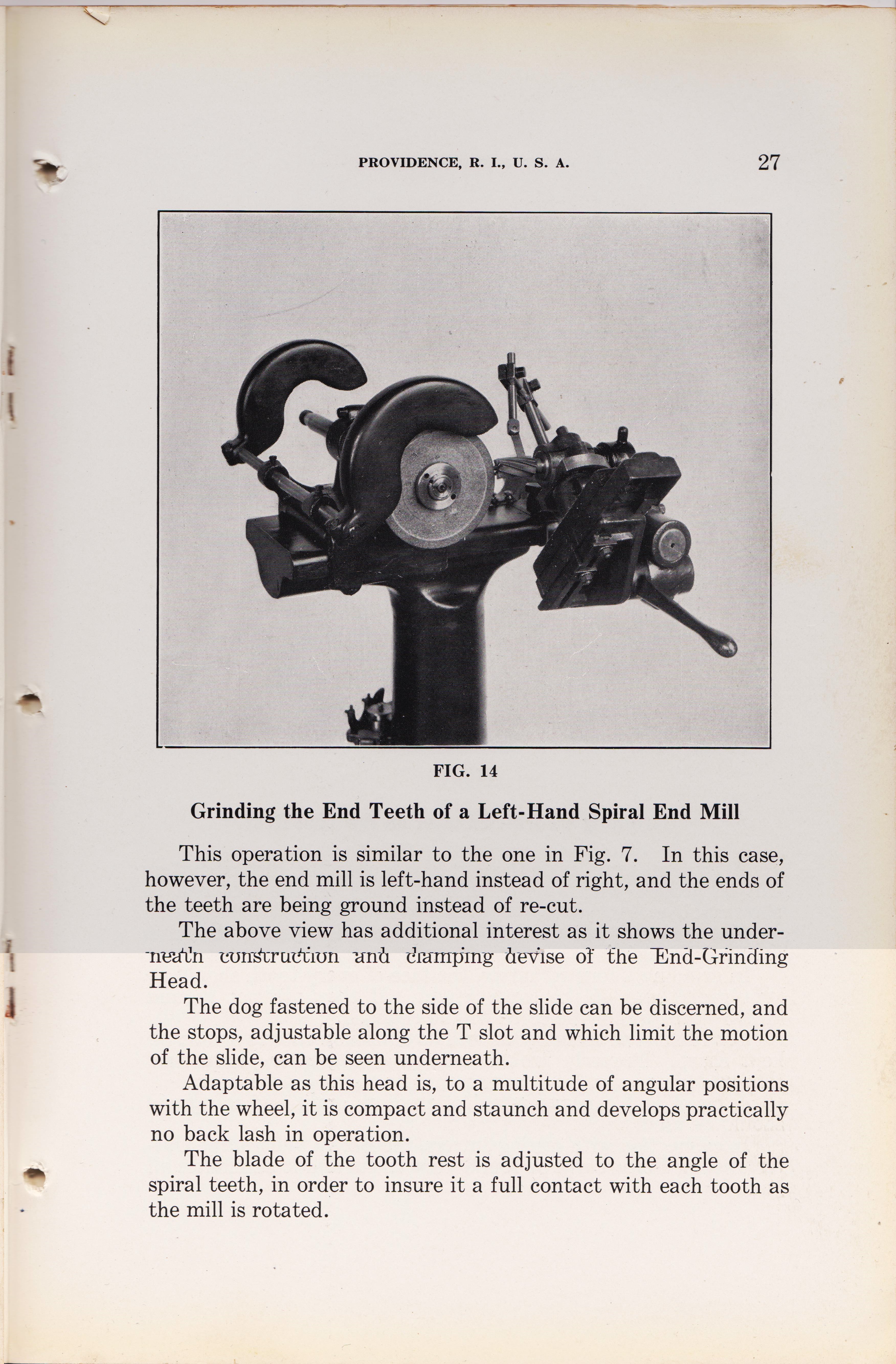
FIG. 14
Grinding the End Teeth of a Left-Hand. Spiral End Mill This operation is similar to the one in Fig. 7. In this case, however, the end mill is left-hand instead of right, and the ends of the teeth are being ground instead of re-cut. The above view has additional interest as it shows the under-- devise of the End-Grinding Head. The dog fastened to the side of the slide can be discerned, and the stops, adjustable along the T slot and which limit the motion of the slide, can be seen underneath. Adaptable as this head is, to a multitude of angular positions with the wheel, it is compact and staunch and develops practically no back lash in operation. The blade of the tooth rest is adjusted to the angle of the spiral teeth, in order to insure it a full contact with each tooth as the mill is rotated.
*********27***********
%%%%%%%%%28%%%%%%%%
page 27 Grinding an Angular Cutter with the End-Grinding Head
#2 Universal Cutter Grinder Machine, BROWN & SHARPE MFG. CO. PROVIDENCE, R. I., U. S. A.
page 26. END-GRINDING HEAD
FIG. 14
Grinding the End Teeth of a Left-Hand. Spiral End Mill This operation is similar to the one in Fig. 7. In this case, however, the end mill is left-hand instead of right, and the ends of the teeth are being ground instead of re-cut. The above view has additional interest as it shows the under-- devise of the End-Grinding Head. The dog fastened to the side of the slide can be discerned, and the stops, adjustable along the T slot and which limit the motion of the slide, can be seen underneath. Adaptable as this head is, to a multitude of angular positions with the wheel, it is compact and staunch and develops practically no back lash in operation. The blade of the tooth rest is adjusted to the angle of the spiral teeth, in order to insure it a full contact with each tooth as the mill is rotated.
How to set up and use the #2 Universal Cutter Grinder Machines, B&S Co. printed 1929.
page 28
#2 Universal Cutter Grinder Machine, BROWN & SHARPE MFG. CO.
PROVIDENCE, R. I., U. S. A. page `26
Universal-Cutter-and-Reamer-Grinder-Machine-Brown-and-Sharpe-Mfg-Co-1929-No2-pg-28-Grinding-a-formed-cutter-tool-rest
"
width="900" height="1250"
page 28
#2 Universal Cutter Grinder Machine, BROWN & SHARPE MFG. CO.
PROVIDENCE, R. I., U. S. A. page `26
Universal-Cutter-and-Reamer-Grinder-Machine-Brown-and-Sharpe-Mfg-Co-1929-No2-pg-28-Grinding-a-formed-cutter-tool-rest
How to set up and use Universal Cutter Grinder Machines, B&S Co. printed 1929.
page 28 Grinding an Angular Cutter with the End-Grinding Head
#2 Universal Cutter Grinder Machine, BROWN & SHARPE MFG. CO. PROVIDENCE, R. I., U. S. A.
page 26. END-GRINDING HEAD
FIG. 14
Grinding the End Teeth of a Left-Hand. Spiral End Mill This operation is similar to the one in Fig. 7. In this case, however, the end mill is left-hand instead of right, and the ends of the teeth are being ground instead of re-cut. The above view has additional interest as it shows the under-- devise of the End-Grinding Head. The dog fastened to the side of the slide can be discerned, and the stops, adjustable along the T slot and which limit the motion of the slide, can be seen underneath. Adaptable as this head is, to a multitude of angular positions with the wheel, it is compact and staunch and develops practically no back lash in operation. The blade of the tooth rest is adjusted to the angle of the spiral teeth, in order to insure it a full contact with each tooth as the mill is rotated.
*********28***********
%%%%%%%%%29%%%%%%%%
page 28 Grinding an Angular Cutter with the End-Grinding Head
#2 Universal Cutter Grinder Machine, BROWN & SHARPE MFG. CO. PROVIDENCE, R. I., U. S. A.
page 26. END-GRINDING HEAD
FIG. 14
Grinding the End Teeth of a Left-Hand. Spiral End Mill This operation is similar to the one in Fig. 7. In this case, however, the end mill is left-hand instead of right, and the ends of the teeth are being ground instead of re-cut. The above view has additional interest as it shows the under-- devise of the End-Grinding Head. The dog fastened to the side of the slide can be discerned, and the stops, adjustable along the T slot and which limit the motion of the slide, can be seen underneath. Adaptable as this head is, to a multitude of angular positions with the wheel, it is compact and staunch and develops practically no back lash in operation. The blade of the tooth rest is adjusted to the angle of the spiral teeth, in order to insure it a full contact with each tooth as the mill is rotated.
How to set up and use the #2 Universal Cutter Grinder Machines, B&S Co. printed 1929.
page 29
#2 Universal Cutter Grinder Machine, BROWN & SHARPE MFG. CO.
PROVIDENCE, R. I., U. S. A. page `26
https://antiquemachinery.com/images-2021/Universal-Cutter-and-Reamer-Grinder-Machine-Brown-and-Sharpe-Mfg-Co-1929-No2-pg-29-Formed-cutter-grinding-Attachment
"
width="900" height="1250"
page 29
#2 Universal Cutter Grinder Machine, BROWN & SHARPE MFG. CO.
PROVIDENCE, R. I., U. S. A. page `26
https://antiquemachinery.com/images-2021/Universal-Cutter-and-Reamer-Grinder-Machine-Brown-and-Sharpe-Mfg-Co-1929-No2-pg-29-Formed-cutter-grinding-Attachment
How to set up and use Universal Cutter Grinder Machines, B&S Co. printed 1929.
page 29 Grinding an Angular Cutter with the End-Grinding Head
#2 Universal Cutter Grinder Machine, BROWN & SHARPE MFG. CO. PROVIDENCE, R. I., U. S. A.
page 29. END-GRINDING HEAD
FIG. 14
Grinding the End Teeth of a Left-Hand. Spiral End Mill This operation is similar to the one in Fig. 7. In this case, however, the end mill is left-hand instead of right, and the ends of the teeth are being ground instead of re-cut. The above view has additional interest as it shows the under-- devise of the End-Grinding Head. The dog fastened to the side of the slide can be discerned, and the stops, adjustable along the T slot and which limit the motion of the slide, can be seen underneath. Adaptable as this head is, to a multitude of angular positions with the wheel, it is compact and staunch and develops practically no back lash in operation. The blade of the tooth rest is adjusted to the angle of the spiral teeth, in order to insure it a full contact with each tooth as the mill is rotated.
*********29***********
%%%%%%%%%30%%%%%%%%
page 29 Grinding an Angular Cutter with the End-Grinding Head
#2 Universal Cutter Grinder Machine, BROWN & SHARPE MFG. CO. PROVIDENCE, R. I., U. S. A.
page 29. END-GRINDING HEAD
FIG. 14
Grinding the End Teeth of a Left-Hand. Spiral End Mill This operation is similar to the one in Fig. 7. In this case, however, the end mill is left-hand instead of right, and the ends of the teeth are being ground instead of re-cut. The above view has additional interest as it shows the under-- devise of the End-Grinding Head. The dog fastened to the side of the slide can be discerned, and the stops, adjustable along the T slot and which limit the motion of the slide, can be seen underneath. Adaptable as this head is, to a multitude of angular positions with the wheel, it is compact and staunch and develops practically no back lash in operation. The blade of the tooth rest is adjusted to the angle of the spiral teeth, in order to insure it a full contact with each tooth as the mill is rotated.
How to set up and use the #2 Universal Cutter Grinder Machines, B&S Co. printed 1929.
page 30
#2 Universal Cutter Grinder Machine, BROWN & SHARPE MFG. CO.
PROVIDENCE, R. I., U. S. A. page `26
Universal-Cutter-and-Reamer-Grinder-Machine-Brown-and-Sharpe-Mfg-Co-1929-No-2
"
width="900" height="1250"
page 30
#2 Universal Cutter Grinder Machine, BROWN & SHARPE MFG. CO.
PROVIDENCE, R. I., U. S. A. page `26
Universal-Cutter-and-Reamer-Grinder-Machine-Brown-and-Sharpe-Mfg-Co-1929-No-2
How to set up and use Universal Cutter Grinder Machines, B&S Co. printed 1929.
page 30 Grinding an Angular Cutter with the End-Grinding Head
#2 Universal Cutter Grinder Machine, BROWN & SHARPE MFG. CO. PROVIDENCE, R. I., U. S. A.
page 30. END-GRINDING HEAD
FIG. 14
Grinding the End Teeth of a Left-Hand. Spiral End Mill This operation is similar to the one in Fig. 7. In this case, however, the end mill is left-hand instead of right, and the ends of the teeth are being ground instead of re-cut. The above view has additional interest as it shows the under-- devise of the End-Grinding Head. The dog fastened to the side of the slide can be discerned, and the stops, adjustable along the T slot and which limit the motion of the slide, can be seen underneath. Adaptable as this head is, to a multitude of angular positions with the wheel, it is compact and staunch and develops practically no back lash in operation. The blade of the tooth rest is adjusted to the angle of the spiral teeth, in order to insure it a full contact with each tooth as the mill is rotated.
*********30***********
*********29***********
%%%%%%%%%32%%%%%%%%
page 30 Grinding an Angular Cutter with the End-Grinding Head
#2 Universal Cutter Grinder Machine, BROWN & SHARPE MFG. CO. PROVIDENCE, R. I., U. S. A.
page 30. END-GRINDING HEAD
FIG. 14
Grinding the End Teeth of a Left-Hand. Spiral End Mill This operation is similar to the one in Fig. 7. In this case, however, the end mill is left-hand instead of right, and the ends of the teeth are being ground instead of re-cut. The above view has additional interest as it shows the under-- devise of the End-Grinding Head. The dog fastened to the side of the slide can be discerned, and the stops, adjustable along the T slot and which limit the motion of the slide, can be seen underneath. Adaptable as this head is, to a multitude of angular positions with the wheel, it is compact and staunch and develops practically no back lash in operation. The blade of the tooth rest is adjusted to the angle of the spiral teeth, in order to insure it a full contact with each tooth as the mill is rotated.
How to set up and use the #2 Universal Cutter Grinder Machines, B&S Co. printed 1929.
page 32
#2 Universal Cutter Grinder Machine, BROWN & SHARPE MFG. CO.
PROVIDENCE, R. I., U. S. A. page `26
Universal-Cutter-and-Reamer-Grinder-Machine-No-2-Brown-and-Sharpe-Mfg-Co-1929-No3-pg-31
"
width="900" height="1250"
page 32
#2 Universal Cutter Grinder Machine, BROWN & SHARPE MFG. CO.
PROVIDENCE, R. I., U. S. A. page `26
Universal-Cutter-and-Reamer-Grinder-Machine-No-2-Brown-and-Sharpe-Mfg-Co-1929-No3-pg-31
How to set up and use Universal Cutter Grinder Machines, B&S Co. printed 1929.
page 32 Grinding an Angular Cutter with the End-Grinding Head
#2 Universal Cutter Grinder Machine, BROWN & SHARPE MFG. CO. PROVIDENCE, R. I., U. S. A.
page 32. END-GRINDING HEAD
FIG. 14
Grinding the End Teeth of a Left-Hand. Spiral End Mill This operation is similar to the one in Fig. 7. In this case, however, the end mill is left-hand instead of right, and the ends of the teeth are being ground instead of re-cut. The above view has additional interest as it shows the under-- devise of the End-Grinding Head. The dog fastened to the side of the slide can be discerned, and the stops, adjustable along the T slot and which limit the motion of the slide, can be seen underneath. Adaptable as this head is, to a multitude of angular positions with the wheel, it is compact and staunch and develops practically no back lash in operation. The blade of the tooth rest is adjusted to the angle of the spiral teeth, in order to insure it a full contact with each tooth as the mill is rotated.
*********32***********
%%%%%%%%%32%%%%%%%%
page 32 Grinding an Angular Cutter with the End-Grinding Head
#2 Universal Cutter Grinder Machine, BROWN & SHARPE MFG. CO. PROVIDENCE, R. I., U. S. A.
page 32. END-GRINDING HEAD
FIG. 14
Grinding the End Teeth of a Left-Hand. Spiral End Mill This operation is similar to the one in Fig. 7. In this case, however, the end mill is left-hand instead of right, and the ends of the teeth are being ground instead of re-cut. The above view has additional interest as it shows the under-- devise of the End-Grinding Head. The dog fastened to the side of the slide can be discerned, and the stops, adjustable along the T slot and which limit the motion of the slide, can be seen underneath. Adaptable as this head is, to a multitude of angular positions with the wheel, it is compact and staunch and develops practically no back lash in operation. The blade of the tooth rest is adjusted to the angle of the spiral teeth, in order to insure it a full contact with each tooth as the mill is rotated.
How to set up and use the #2 Universal Cutter Grinder Machines, B&S Co. printed 1929.
page 32
#2 Universal Cutter Grinder Machine, BROWN & SHARPE MFG. CO.
PROVIDENCE, R. I., U. S. A. page `26
Universal-Cutter-and-Reamer-Grinder-Machine-No-2-Brown-and-Sharpe-Mfg-Co-1929-No3-pg-31
"
width="900" height="1250"
page 32
#2 Universal Cutter Grinder Machine, BROWN & SHARPE MFG. CO.
PROVIDENCE, R. I., U. S. A. page `26
Universal-Cutter-and-Reamer-Grinder-Machine-No-2-Brown-and-Sharpe-Mfg-Co-1929-No3-pg-31
How to set up and use Universal Cutter Grinder Machines, B&S Co. printed 1929.
page 32 Grinding an Angular Cutter with the End-Grinding Head
#2 Universal Cutter Grinder Machine, BROWN & SHARPE MFG. CO. PROVIDENCE, R. I., U. S. A.
page 32. END-GRINDING HEAD
FIG. 14
Grinding the End Teeth of a Left-Hand. Spiral End Mill This operation is similar to the one in Fig. 7. In this case, however, the end mill is left-hand instead of right, and the ends of the teeth are being ground instead of re-cut. The above view has additional interest as it shows the under-- devise of the End-Grinding Head. The dog fastened to the side of the slide can be discerned, and the stops, adjustable along the T slot and which limit the motion of the slide, can be seen underneath. Adaptable as this head is, to a multitude of angular positions with the wheel, it is compact and staunch and develops practically no back lash in operation. The blade of the tooth rest is adjusted to the angle of the spiral teeth, in order to insure it a full contact with each tooth as the mill is rotated.
*********32***********
%%%%%%%%%33%%%%%%%%
9'th pic down text
page 32 Grinding an Angular Cutter with the End-Grinding Head
#2 Universal Cutter Grinder Machine, BROWN & SHARPE MFG. CO. PROVIDENCE, R. I., U. S. A.
page 32. END-GRINDING HEAD
FIG. 14
Grinding the End Teeth of a Left-Hand. Spiral End Mill This operation is similar to the one in Fig. 7. In this case, however, the end mill is left-hand instead of right, and the ends of the teeth are being ground instead of re-cut. The above view has additional interest as it shows the under-- devise of the End-Grinding Head. The dog fastened to the side of the slide can be discerned, and the stops, adjustable along the T slot and which limit the motion of the slide, can be seen underneath. Adaptable as this head is, to a multitude of angular positions with the wheel, it is compact and staunch and develops practically no back lash in operation. The blade of the tooth rest is adjusted to the angle of the spiral teeth, in order to insure it a full contact with each tooth as the mill is rotated.
11xth pic down
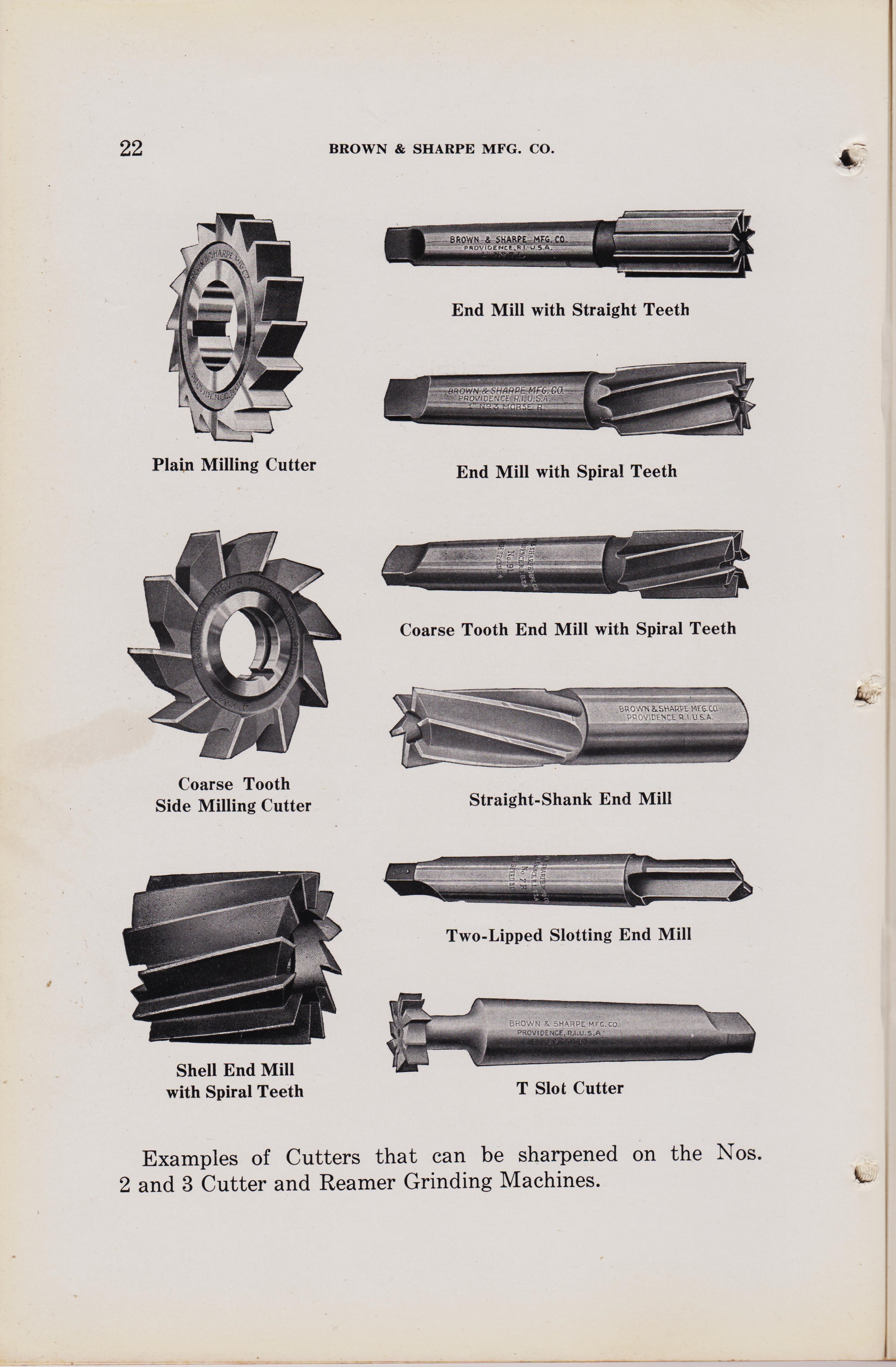
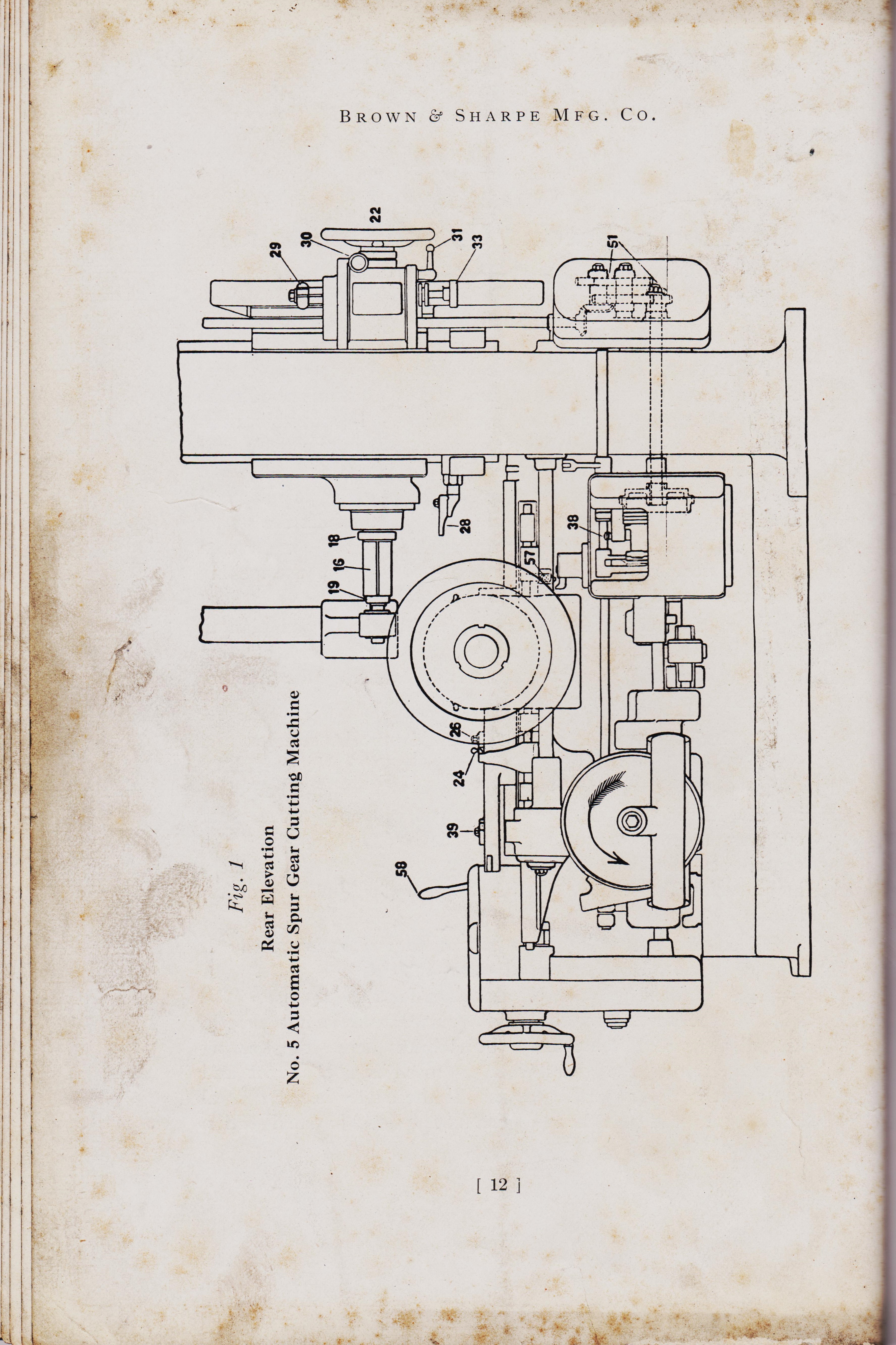
Automatic-Gear-Cutting-Machines-Brown-and-Sharpe-Mfg-Co-1914-pg-11-
Indicator for setting up the cutter that came-with-origional-gear-cutting machine.
page 12 top
/ 10'th pic down
Automatic-Gear-Cutting-Machines-Brown-and-Sharpe-Mfg-Co-1914-pg-13-
Indicator for setting up the cutter that came-with-origional-gear-cutting machine.
page 12 top
BROWN & SHARPE MFG. CO. page 11
Method of Setting Up and Operating a Spur Gear Cutting Machine
Adjusting Index Change Gears. First the proper change gears for the required number of divisions should be put in place on the indexing mechanism. The combinations necessary for different divisions are specified in the table sent with the machine, also on pages 50, 51, 52, 53 and 54, while the position of the change gears on the machine is indicated at 51, Fig. 1.
Fasten the gears in position, then lift the spring knob 38, Fig. 1,
and set the sliding block at the numbered recess corresponding with the number of turns of the locking disk required as given in the index table. When the gearing has been adjusted, it is a good plan to prove it to be correct by marking the index wheel, starting the machine and indexing it around, counting the number of teeth that will be cut.
Setting Cutter.
The cutter should now be selected and firmly secured on the arbor. In this position, it should be tested for true running, both at the side and periphery. If it runs out at the side, the grooves cut will not be the exact contour of the cutter teeth, and if it is eccentric, all of the cutting strain will be brought upon a few teeth. Unless these inaccuracies are minute or can be remedied another cutter should be used. When the cutter has been found to run satisfactorily it should be set exactly central with the work spindle. An indicator is furnished with all machines for this purpose. The sides of the teeth produced by a cutter that is not exactly central vary with relation to radial lines; hence the bearing on the teeth of the gears when in mesh is not correct and the result is noisy running gears. If the cutter is not central it will be noticed that the gears run more quietly in one direction than the other. *********
page 13****BROWN & SHARPE MFG. CO. To set the cutter central, loosen nut 15, Fig. 3, and, after removing the dust guard, clamp the indicator, Fig. 2,
to the ways of the bed in front of the cutter slide, in a position to allow the screw J to be adjusted so the point will touch the cutter about on the pitch line. Indicate the opposite sides of the cutter by reversing the arm K on the pin L.
Fig. 2 Indicator for Setting Cutter Adjust the cutter spindle by means of the worm 14, Fig. 3,
until the zero on arm K is equidistant from zero on the plate when the arm K is in either position, then clamp with nut 15, Fig. 3.
If preferred, the screw J can be adjusted so that when cutter is central, the two zero lines will be together in both positions of the arm.
[ 13
***************************
&&&&&&&&&&&&&&&&&&
12 page 1 top
Automatic-Gear-Cutting-Machines-Brown-and-Sharpe-Mfg-Co-1914-pg-11-
Indicator for setting up the cutter that came-with-origional-gear-cutting machine.
page 12 top
/ 10'th pic down
Automatic-Gear-Cutting-Machines-Brown-and-Sharpe-Mfg-Co-1914-pg-13-
Indicator for setting up the cutter that came-with-origional-gear-cutting machine.
page 12 top
BROWN & SHARPE MFG. CO. page 11
Method of Setting Up and Operating a Spur Gear Cutting Machine
Adjusting Index Change Gears. First the proper change gears for the required number of divisions should be put in place on the indexing mechanism. The combinations necessary for different divisions are specified in the table sent with the machine, also on pages 50, 51, 52, 53 and 54, while the position of the change gears on the machine is indicated at 51, Fig. 1.
Fasten the gears in position, then lift the spring knob 38, Fig. 1,
and set the sliding block at the numbered recess corresponding with the number of turns of the locking disk required as given in the index table. When the gearing has been adjusted, it is a good plan to prove it to be correct by marking the index wheel, starting the machine and indexing it around, counting the number of teeth that will be cut.
Setting Cutter.
The cutter should now be selected and firmly secured on the arbor. In this position, it should be tested for true running, both at the side and periphery. If it runs out at the side, the grooves cut will not be the exact contour of the cutter teeth, and if it is eccentric, all of the cutting strain will be brought upon a few teeth. Unless these inaccuracies are minute or can be remedied another cutter should be used. When the cutter has been found to run satisfactorily it should be set exactly central with the work spindle. An indicator is furnished with all machines for this purpose. The sides of the teeth produced by a cutter that is not exactly central vary with relation to radial lines; hence the bearing on the teeth of the gears when in mesh is not correct and the result is noisy running gears. If the cutter is not central it will be noticed that the gears run more quietly in one direction than the other. *********
page 13****BROWN & SHARPE MFG. CO. To set the cutter central, loosen nut 15, Fig. 3, and, after removing the dust guard, clamp the indicator, Fig. 2,
to the ways of the bed in front of the cutter slide, in a position to allow the screw J to be adjusted so the point will touch the cutter about on the pitch line. Indicate the opposite sides of the cutter by reversing the arm K on the pin L.
Fig. 2 Indicator for Setting Cutter Adjust the cutter spindle by means of the worm 14, Fig. 3,
until the zero on arm K is equidistant from zero on the plate when the arm K is in either position, then clamp with nut 15, Fig. 3.
If preferred, the screw J can be adjusted so that when cutter is central, the two zero lines will be together in both positions of the arm.
[ 13
https://antiquemachinery.com/images-2020/Automatic-Gear-Cutting-Machines-Brown-and-Sharpe-Mfg-Co-1914-pg-1-.jpg
201 https://antiquemachinery.com/images-2020/Automatic-Gear-Cutting-Machines-Brown-and-Sharpe-Mfg-Co-1914-pg-12-Rear-Elevation-Drawing.jpg
Sixth pic down
Care and Use of Automatic Gear Cutting Machines For Spur and Bevel Gears.
HELICAL GEARING.
/ Care and Use of Automatic Gear Cutting Machines For Spur and Bevel Gears.
TRADE MARK
Brown & Sharpe Mfg. Co. Providence, R. I., U. S. A.
Fig. 1 Rear Elevation
No. 5 Automatic Spur Gear Cutting Machine
page 19
88888888888888
page 9
Care and Use of Automatic Gear Cutting Machines For Spur and Bevel Gears.
HELICAL GEARING.
/ Care and Use of Automatic Gear Cutting Machines For Spur and Bevel Gears.
TRADE MARK
Brown & Sharpe Mfg. Co. Providence, R. I., U. S. A.
Fig. 1 Rear Elevation
No. 5 Automatic Spur Gear Cutting Machine
page 19
Fig. 3 Plan No. 5 Automatic Spur Gear Cutting Machine
Automatic-Gear-Cutting-Machines-Brown-and-Sharpe-Mfg-Co-1914-pg-9-Care-of-the-Gear-Cutting-Machines
/ Fig. 3 Plan No. 5 Automatic Spur Gear Cutting Machine
******************************
Automatic-Gear-Cutting-Machines-Brown-and-Sharpe-Mfg-Co-1914-pg-15-How-to-set-up-Gear-Cutting-Machine.jpg
Automatic-Gear-Cutting-Machines-Brown-and-Sharpe-Mfg-Co-1914-pg-9-Care-of-the-Gear-Cutting-Machines
/ Fig. 3 Plan No. 5 Automatic Spur Gear Cutting Machine
/
BROWN & SHARPE MFG. CO.
Raising Work Slide by Power. The work slide of Nos. 5 and 6 Machines may be raised and lowered by power. All clamps should be loosened in the slide and the hand elevating crank removed, then the slide can be moved to the height desired by means of the lever on the bed in front of the column. Adjustment of Work Arbor. Placing the work in the Nos. 5 and 6 Spur Gear Cutting Machines, where the with-drawing expansion arbor is employed, is accomplished by removing nut 19, Figs. 1 and 4. Then with nut 18 force the bushing 16 off the arbor. To release the work arbor, loosen the spring collet by screwing the nut 18 against the end of spindle and then by taking hold of the hand wheel 22, Figs. 1 and 4, the arbor can be drawn back through the spindle.
Fig. 4 Section through Work Spindle, showing Withdrawing Expansion Arbor
Insert the bushing 16 into bore of the gear blank and place in position.. Push the work arbor forward through the bushing and screw nut 19 against the bushing, expanding it solidly in the bore of gear blank. Loosen nut 18 a little and with the hand wheel 22 draw the arbor and collet securely into the taper hole in spindle. To take out arbor, remove the hand wheel 22 and the screw 52, Fig. 4; the arbor can then be drawn out in direction indi-cated by arrow. Either expansion work arbors or solid arbors can be used in any of the machines. Expansion arbors are not furnished
pg[ 15 ]
title text
((((((((((((((((((((((((((((((((((((((((((((((((((((((((((((((
Automatic-Gear-Cutting-Machines-Brown-and-Sharpe-Mfg-Co-1914-pg-15-How-to-set-up-Gear-Cutting-Machine.jpg
Raising Work Slide by Power. The work slide of Nos. 5 and 6 Machines may be raised and lowered by power. All clamps should be loosened in the slide and the hand elevating crank removed, then the slide can be moved to the height desired by means of the lever on the bed in front of the column. Adjustment of Work Arbor. Placing the work in the Nos. 5 and 6 Spur Gear Cutting Machines, where the with-drawing expansion arbor is employed, is accomplished by removing nut 19, Figs. 1 and 4. Then with nut 18 force the bushing 16 off the arbor. To release the work arbor, loosen the spring collet by screwing the nut 18 against the end of spindle and then by taking hold of the hand wheel 22, Figs. 1 and 4, the arbor can be drawn back through the spindle.
Fig. 4 Section through Work Spindle, showing Withdrawing Expansion Arbor
Insert the bushing 16 into bore of the gear blank and place in position.. Push the work arbor forward through the bushing and screw nut 19 against the bushing, expanding it solidly in the bore of gear blank. Loosen nut 18 a little and with the hand wheel 22 draw the arbor and collet securely into the taper hole in spindle. To take out arbor, remove the hand wheel 22 and the screw 52, Fig. 4; the arbor can then be drawn out in direction indi-cated by arrow. Either expansion work arbors or solid arbors can be used in any of the machines. Expansion arbors are not furnished
pg[ 15 ]
Page 16 Automatic-Gear-Cutting-Machines-Brown-and-Sharpe-Mfg-Co-1914-page-16-How-to-set-up-Gear-Cutting-Machine
/
BROWN & SHARPE MFG. CO.
with the Nos. 3 and 4 Machines, but can be supplied when desired. Where the expansion arbor is not used, .a solid arbor must be selected that closely fits the hole in the blank. Care should be taken that it runs true on centres and is also true when firmly secured in the hole in the work spindle. To get accurate gears an arbor should not run out over one-half of one-thousandth of an inch.
Setting the Blank.
Before placing the blank upon the arbor the outside diameter should be measured and compared with the correct outside diameter for the pitch and number of teeth to be cut. If it is a little under size, compensation should be made in setting the gear tooth caliper for depth to pitch lineone-half the amount the blank is under size should be taken from the depth to the pitch line. If the blank is over size it should be returned to the lathe and reduced to the proper diameter. Test the blank for true running while it is loose upon the arbor. If it runs out very much either discard it or have the inaccuracy remedied; but if it is slight, mark the high spot and be sure it comes in the same place when the blank is tightened up; the pitch circle will then be concentric with the center hole. To test the gear when it has been tightened up, disconnect the index worm by loosening the clamping lever 31, Fig. 1, and turning the knob 30; then turn the wheel by hand. Also test the side of the gear to see that it does not wabble, or bind against the rim rest if one is used. When this has been done, and the index worm returned to its working position in the wheel, trip the indexing mechanism once after starting the machine in order to take up any backlash in the gears.
Selecting Change Gears for Cutter Spindle Speed.
While exact cutter speeds cannot be given, owing to variation in the conditions surrounding the work, the following suggestions may be found helpful to the inexperienced operator. Under average conditions carbon steel cutters may be run from 60 to 70 feet per minute in cast iron, and from 30 to 40 feet per minute in machinery steel. [ 16 ]
href https://antiquemachinery.com/images-2020/Automatic-Gear-Cutting-Machines-Brown-and-Sharpe-Mfg-Co-1914-pg-1-.jpg
text pg 17
/
BROWN & SHARPE MFG. CO.
High-speed steel cutters can be run from 80 to 125 feet per minute in cast iron, and from 65 to 100 feet per minute in machinery steel. It should be borne in mind that the speed of the cutter may be anywhere within these limits, or even in extreme instances greater or less. It varies in every case according to the quality of material to be cut, accuracy of finish desired, rigidity of gear blank and kind of lubricant used. All these factors should be considered when deciding on the cutter speed. For tables of revolutions per minute for various cutting speeds and diameters, see pages 60 and 61. The change gears necessary to give the speed desired, as indicated on the speed table furnished with the machine, are placed in position as shown at 53,
Fig. 3. For tables of speeds and feeds, see pages 55, 56, 57, 58 and 59. Feed of Cutter Slide. The rate of feed varies so widely under different conditions, while slight changes have so marked an effect on the cost and quality of the product, that no exact rates can be given as the correct ones. The best method is to start with a moderate feed, then increase it until the gear blank will stand no more or the economical limit of the cutter is reached. The frequency with which the cutter must be ground to keep it in good condition shows whether it is being driven nearly to its limit. If it becomes dull very quickly, the feed is probably too fast and should be reduced, there being danger of burning the cutter. On the other hand, a cutter that runs long periods without becoming dull may safely be fed faster. The most economical feed is usually not the fastest which the cutter will stand without burning or breaking. This is due to the fact that with a very high rate of feed the cutter must be ground frequently, which consumes considerable time. There is also the risk of a ruined cutter. A slightly slower feed in such a case will not greatly decrease the rate of production, while it will, on the other hand, cause the cutter to hold its edge several times as long, as a rule. The result is that the net production per cutter will be greater at the slower feed and the production per day may be as great. This reduces the cutter cost per gear produced, since the cutters last much longer under the slightly slower feed. [ 17 ]
+++++++++++++++++
High-speed steel cutters can be run from 80 to 125 feet per minute in cast iron, and from 65 to 100 feet per minute in machinery steel. It should be borne in mind that the speed of the cutter may be anywhere within these limits, or even in extreme instances greater or less. It varies in every case according to the quality of material to be cut, accuracy of finish desired, rigidity of gear blank and kind of lubricant used. All these factors should be considered when deciding on the cutter speed. For tables of revolutions per minute for various cutting speeds and diameters, see pages 60 and 61. The change gears necessary to give the speed desired, as indicated on the speed table furnished with the machine, are placed in position as shown at 53,
Fig. 3. For tables of speeds and feeds, see pages 55, 56, 57, 58 and 59. Feed of Cutter Slide. The rate of feed varies so widely under different conditions, while slight changes have so marked an effect on the cost and quality of the product, that no exact rates can be given as the correct ones. The best method is to start with a moderate feed, then increase it until the gear blank will stand no more or the economical limit of the cutter is reached. The frequency with which the cutter must be ground to keep it in good condition shows whether it is being driven nearly to its limit. If it becomes dull very quickly, the feed is probably too fast and should be reduced, there being danger of burning the cutter. On the other hand, a cutter that runs long periods without becoming dull may safely be fed faster. The most economical feed is usually not the fastest which the cutter will stand without burning or breaking. This is due to the fact that with a very high rate of feed the cutter must be ground frequently, which consumes considerable time. There is also the risk of a ruined cutter. A slightly slower feed in such a case will not greatly decrease the rate of production, while it will, on the other hand, cause the cutter to hold its edge several times as long, as a rule. The result is that the net production per cutter will be greater at the slower feed and the production per day may be as great. This reduces the cutter cost per gear produced, since the cutters last much longer under the slightly slower feed. [ 17 ]
Automatic-Gear-Cutting-Machines-Brown-and-Sharpe-Mfg-Co-1914-page-18-How-to-set-up-Gear-Cutting-Machine.jpg.
Brown & Sharpe Mfg. Co. Providence, R. I., U. S. A.
Feed Of High-Speed-Cutters
Setting Reversing-Dogs
Ajusting for Depth of Tooth
page 18
Brown & Sharpe Mfg. Co. Providence, R. I., U. S. A.
Feed Of High-Speed-Cutters
Setting Reversing-Dogs
Ajusting for Depth of Tooth
page 18
/
BROWN & SHARPE MFG. CO.
Since most of the cutters used in manufacturing are of high-speed steel, the following table will give useful data for the feed of these cutters:
Feed of High-Speed Steel Cutters
Diametral Pitch 2
Feed, Inches per Minute
Cast I. Steel
A table furnished with each machine indicates the change gears to be used for the desired feed, their position being shown at 54, Fig. 3. The Transposing Gears, which are behind the feed change gears, should not be removed except when changing from the coarser to the finer feeds, as noted in Feed Table.
Setting Reversing Dogs.
Move the cutter slide for-ward, leaving enough space between the cutter and work for indexing, and clamp the reversing dog 26, Fig. 1, while resting against the reversing arm. Turn up the index trip dog 57, Fig. 1, so that the machine will not index and spoil the blank while adjusting the stroke. Start the machine and throw in the feed by means of the lever 58, Fig. 1, which should be thrown as far forward as it will go. The feed dog tappet 24, Fig. 1, can be swung back out of the way to allow the slide to travel to the extreme end of bed before reversing. When the center of the cutter has nearly reached the forward edge of the work, clamp the dog 39, Fig. 1, while it is resting against the reversing arm. It may be necessary to adjust the dogs slightly after this to avoid loss of time at the ends of travel of the cutter slide. Adjusting for Depth of Tooth. Move the feed throw-out lever 58, Fig. 1, as far back as it will go and run the cutter slide forward by hand until the cutter is under blank. Loosen all the clamps on the work spindle slide and outer support, lower the blank by means of the hand wheel or crank
[18]
+++++++++++++++++++
+++++++++++++++++
Since most of the cutters used in manufacturing are of high-speed steel, the following table will give useful data for the feed of these cutters:
Feed of High-Speed Steel Cutters
Diametral Pitch 2
Feed, Inches per Minute
Cast I. Steel
A table furnished with each machine indicates the change gears to be used for the desired feed, their position being shown at 54, Fig. 3. The Transposing Gears, which are behind the feed change gears, should not be removed except when changing from the coarser to the finer feeds, as noted in Feed Table.
Setting Reversing Dogs.
Move the cutter slide for-ward, leaving enough space between the cutter and work for indexing, and clamp the reversing dog 26, Fig. 1, while resting against the reversing arm. Turn up the index trip dog 57, Fig. 1, so that the machine will not index and spoil the blank while adjusting the stroke. Start the machine and throw in the feed by means of the lever 58, Fig. 1, which should be thrown as far forward as it will go. The feed dog tappet 24, Fig. 1, can be swung back out of the way to allow the slide to travel to the extreme end of bed before reversing. When the center of the cutter has nearly reached the forward edge of the work, clamp the dog 39, Fig. 1, while it is resting against the reversing arm. It may be necessary to adjust the dogs slightly after this to avoid loss of time at the ends of travel of the cutter slide. Adjusting for Depth of Tooth. Move the feed throw-out lever 58, Fig. 1, as far back as it will go and run the cutter slide forward by hand until the cutter is under blank. Loosen all the clamps on the work spindle slide and outer support, lower the blank by means of the hand wheel or crank
[18]
/
BROWN & SHARPE MFG. CO.
at 21, Fig. 3, until the cutter, which should be running, just touches the blank. Move the cutter slide back by throwing the reversing lever 27, Fig. 3, to the right until the cutter will clear the blank. To take out any backlash there may be in the elevating screw, turn the hand wheel or crank a little in the opposite direction. Set the dial 20, Fig. 3, at zero, then lower the work spindle slide a little more than the depth required and raise it until the dial 20, will read the proper depth for the pitch to be cut, making proper allowance in case the blank is turned too small. By this method the weight of the various parts will rest upon the screw and the slide will be less likely to change position when clamping. After the work is properly set, clamp the work spindle slide first and then the outer support. In tightening the work slide be sure to tighten the bolts on the left-hand side of the head and then tighten those on the right-hand side, as this brings the work spindle slide up into position in case a heavy blank has caused it to sag when the bolts were loosened.
Setting Rim Rest. Place the rim rest shown at 28, Fig. 1, in position, setting it high enough to clear the cutter. Care should be taken that the rim rest does not bind the blank at any point. To test the adjustment of the rim rest, disengage the worm and wheel and turn the work spindle by hand. After testing the adjustment engage the worm and wheel again and clamp securely by means of handle 31, Fig. 1.
Taking Trial Cuts.
The machine is now ready to take trial cuts. Allow the cutter to advance far enough into the blank to give the groove its full form for a short distance; then reverse it, index one space, and make a similar cut.
When the two trial grooves are cut, trip the indexing mechanism until they are brought into a position where it is possible to measure them. Measure the tooth for thickness at the pitch line. If it is not quite the required thickness, adjust the work slide a little and take trial cuts until the correct thickness is obtained, then go ahead and cut completely around.
[ 19 ]
+++++++++++++++++++
11 pic down text
at 21, Fig. 3, until the cutter, which should be running, just touches the blank. Move the cutter slide back by throwing the reversing lever 27, Fig. 3, to the right until the cutter will clear the blank. To take out any backlash there may be in the elevating screw, turn the hand wheel or crank a little in the opposite direction. Set the dial 20, Fig. 3, at zero, then lower the work spindle slide a little more than the depth required and raise it until the dial 20, will read the proper depth for the pitch to be cut, making proper allowance in case the blank is turned too small. By this method the weight of the various parts will rest upon the screw and the slide will be less likely to change position when clamping. After the work is properly set, clamp the work spindle slide first and then the outer support. In tightening the work slide be sure to tighten the bolts on the left-hand side of the head and then tighten those on the right-hand side, as this brings the work spindle slide up into position in case a heavy blank has caused it to sag when the bolts were loosened.
Setting Rim Rest. Place the rim rest shown at 28, Fig. 1, in position, setting it high enough to clear the cutter. Care should be taken that the rim rest does not bind the blank at any point. To test the adjustment of the rim rest, disengage the worm and wheel and turn the work spindle by hand. After testing the adjustment engage the worm and wheel again and clamp securely by means of handle 31, Fig. 1.
Taking Trial Cuts.
The machine is now ready to take trial cuts. Allow the cutter to advance far enough into the blank to give the groove its full form for a short distance; then reverse it, index one space, and make a similar cut.
When the two trial grooves are cut, trip the indexing mechanism until they are brought into a position where it is possible to measure them. Measure the tooth for thickness at the pitch line. If it is not quite the required thickness, adjust the work slide a little and take trial cuts until the correct thickness is obtained, then go ahead and cut completely around.
[ 19 ]
Automatic-Gear-Cutting-Machines-Brown-and-Sharpe-Mfg-Co-1914-page-20-How-to-set-up-Gear-Cutting-Machine
page 19
+++++++++++++++++
page 19
Automatic-Gear-Cutting-Machines-Brown-and-Sharpe-Mfg-Co-1914-page-20 Micrometer measuring Gear-Cutting-Machine.jpg.
A
page 20
A
page 20
/
BROWN C SHARPE MFG. CO.
Gauging Teeth.
To measure or gauge the teeth of a gear while in a machine, lift the feed dog tappet 24, Fig. 1, to clear the reversing arm, and run the cutter slide back out of the way. A gear tooth caliper as shown in Fig. 9 is a very desirable tool for this purpose. The adjustments of the dogs 26 and 39, Fig. 1, need not be altered and the tappet 24 will automatically take its proper position when the cutter slide is run forward.
Re-Cutting Gears.
If it is desired to re-cut a gear or to cut out a bad place in the blank after it has been secured on the arbor, loosen the clamp screw 29, Fig. 1, and adjust the blank to the proper position by turning the knob 33, then clamp with the screw 29. Depth of Gear Tooth Micrometer No. 249
0=9,1,6=6 For Scribing the Whole Depth of Space on Gear Blanks [ 20 ]
$$$$$$$$$$$$$$$$$$$$$$$$$$$$$$$$$$$$$
Gauging Teeth.
To measure or gauge the teeth of a gear while in a machine, lift the feed dog tappet 24, Fig. 1, to clear the reversing arm, and run the cutter slide back out of the way. A gear tooth caliper as shown in Fig. 9 is a very desirable tool for this purpose. The adjustments of the dogs 26 and 39, Fig. 1, need not be altered and the tappet 24 will automatically take its proper position when the cutter slide is run forward.
Re-Cutting Gears.
If it is desired to re-cut a gear or to cut out a bad place in the blank after it has been secured on the arbor, loosen the clamp screw 29, Fig. 1, and adjust the blank to the proper position by turning the knob 33, then clamp with the screw 29. Depth of Gear Tooth Micrometer No. 249
0=9,1,6=6 For Scribing the Whole Depth of Space on Gear Blanks [ 20 ]
Automatic-Gear-Cutting-Machines-Brown-and-Sharpe-Mfg-Co-1914-page-20 Micrometer measuring Gear-Cutting-Machine.jpg.
A
page 20
A
page 20
/
BROWN C SHARPE MFG. CO.
Gauging Teeth.
To measure or gauge the teeth of a gear while in a machine, lift the feed dog tappet 24, Fig. 1, to clear the reversing arm, and run the cutter slide back out of the way. A gear tooth caliper as shown in Fig. 9 is a very desirable tool for this purpose. The adjustments of the dogs 26 and 39, Fig. 1, need not be altered and the tappet 24 will automatically take its proper position when the cutter slide is run forward.
Re-Cutting Gears.
If it is desired to re-cut a gear or to cut out a bad place in the blank after it has been secured on the arbor, loosen the clamp screw 29, Fig. 1, and adjust the blank to the proper position by turning the knob 33, then clamp with the screw 29. Depth of Gear Tooth Micrometer No. 249
Depth of Gear Tooth Micrometer.
For Scribing the Whole Depth of Space on Gear Blanks
[ 20 ]
$$$$$$$$$$$$$$$$$$$$$$$$$$$$$$
$$$$$$ brochere
Gauging Teeth.
To measure or gauge the teeth of a gear while in a machine, lift the feed dog tappet 24, Fig. 1, to clear the reversing arm, and run the cutter slide back out of the way. A gear tooth caliper as shown in Fig. 9 is a very desirable tool for this purpose. The adjustments of the dogs 26 and 39, Fig. 1, need not be altered and the tappet 24 will automatically take its proper position when the cutter slide is run forward.
Re-Cutting Gears.
If it is desired to re-cut a gear or to cut out a bad place in the blank after it has been secured on the arbor, loosen the clamp screw 29, Fig. 1, and adjust the blank to the proper position by turning the knob 33, then clamp with the screw 29. Depth of Gear Tooth Micrometer No. 249
Depth of Gear Tooth Micrometer.
For Scribing the Whole Depth of Space on Gear Blanks
[ 20 ]