
Cream Seperator Machining in 1912 American Machinist Magazine 109 years ago...
..
They made machines......to make machines,
........to make Cream-Separators in 1912?
Hmmmmm......Do I want a spend all my $$$ on a Model T,
or a Cream Separator for my farm?
https://worldhistoryproject.org/1912
Apr 14 1912 RMS Titanic Sinks after Striking an Iceberg
1912 Joseph Stalin Becomes Editor of 'Pravda' Stalin served as the editor of Pravda {Truth} in 1913 and wrote his first treatise, Marxism and the National Question in 1914.
The Progressive Party Is Born
On the evening of June 22, 1912, former President Theodore Roosevelt asked his supporters to leave the floor of the Republican National Convention
The Republican Progressives promised to increase federal regulation and protect the welfare of ordinary people.
Roosevelt maintained that President William Howard Taft had allowed fraudulent seating of delegates in order to capture the presidential nomination (Pre Trump in 1912)
Progressivism is a political and social term that refers to ideologies and movements favoring or advocating changes or reform,
usually in a statist or egalitarian direction for economic policies (government management) and liberal direction for social policies (personal choice).
Progressivism is often viewed in opposition to conservative ideologies.
Aug 1912
Jane Addams seconds Theodore Roosevelt's nomination for the Progressive Party
At the first national convention of the Progressive Party, in Chicago in August of 1912,
all observers noted the prominence of women, women
https://antiquemachinery.com/images-Cream-Separator/1912-American-Machinist-Magazine-1912-June-30-pg-973-Cream-Separator-Plant-55per.jpg
i st half DP pic
They made machines......to make machines,
........to make Cream-Separators in 1912?
Hmmmmm......Do I want a spend all my $$$ on a Model T,
or a Cream Separator for my farm?
https://worldhistoryproject.org/1912
Apr 14 1912 RMS Titanic Sinks after Striking an Iceberg
1912 Joseph Stalin Becomes Editor of 'Pravda' Stalin served as the editor of Pravda {Truth} in 1913 and wrote his first treatise, Marxism and the National Question in 1914.
The Progressive Party Is Born
On the evening of June 22, 1912, former President Theodore Roosevelt asked his supporters to leave the floor of the Republican National Convention
The Republican Progressives promised to increase federal regulation and protect the welfare of ordinary people.
Roosevelt maintained that President William Howard Taft had allowed fraudulent seating of delegates in order to capture the presidential nomination (Pre Trump in 1912)
Progressivism is a political and social term that refers to ideologies and movements favoring or advocating changes or reform,
usually in a statist or egalitarian direction for economic policies (government management) and liberal direction for social policies (personal choice).
Progressivism is often viewed in opposition to conservative ideologies.
Aug 1912
Jane Addams seconds Theodore Roosevelt's nomination for the Progressive Party
At the first national convention of the Progressive Party, in Chicago in August of 1912,
all observers noted the prominence of women, women
AMERICAN MACHINIST 1912
June, 20, 1912 AMERICAN MACHINIST 973
Tools in a Cream Separator Plant
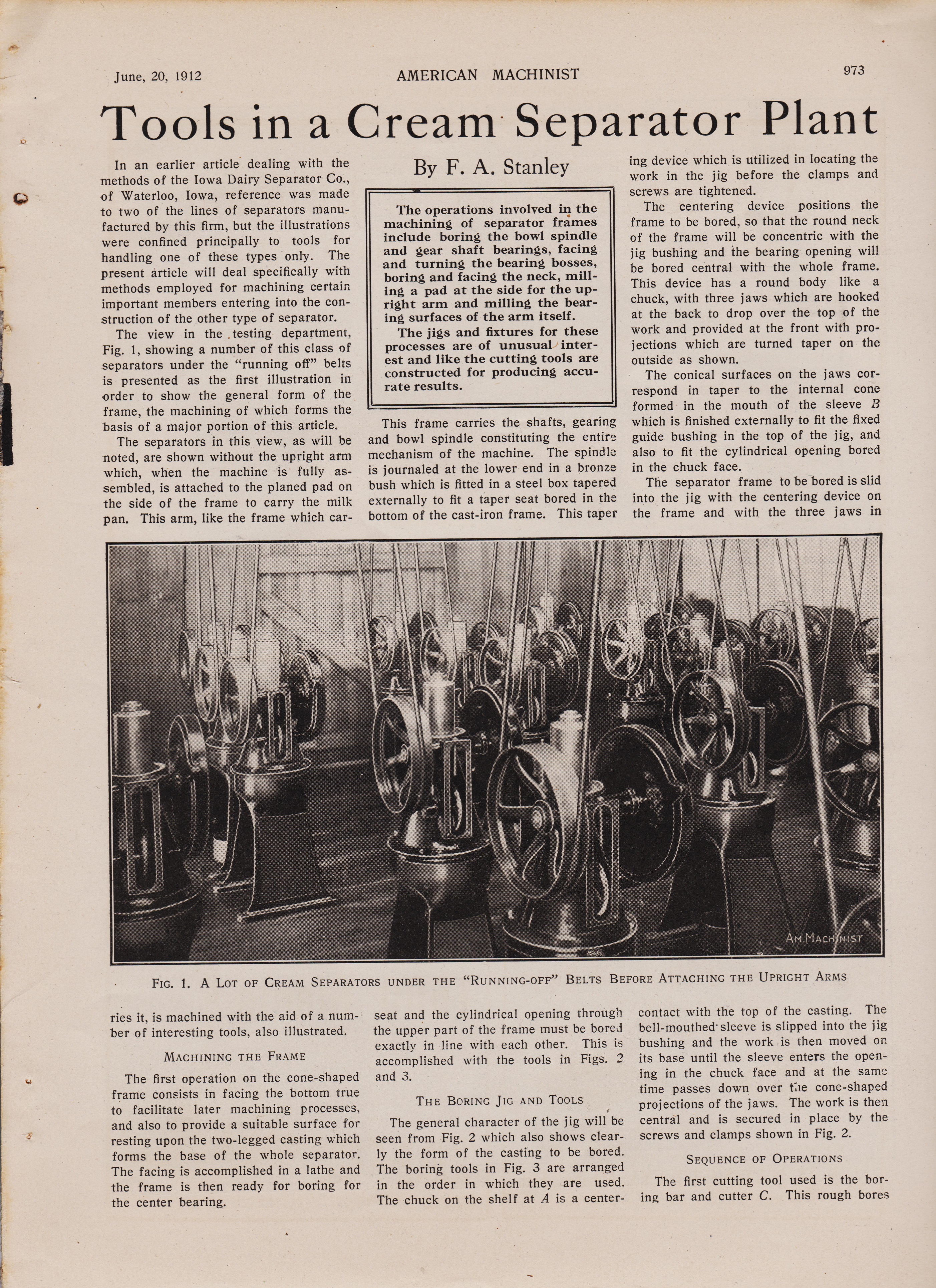
In an earlier article dealing with the methods of the Iowa Dairy Separator Co., of Waterloo, Iowa, reference was made to two of the lines of separators manu-factured by this firm, but the illustrations were confined principally to tools for handling one of these types only. The present article will deal specifically with methods employed for machining certain important members entering into the con-struction of the other type of separator. The view in the . testing department, Fig. 1, showing a number of this class of separators under the "running off" belts is presented as the first illustration in order to show the general form of the frame, the machining of which forms the basis of a major portion of this article. The separators in this view, as will be noted, are shown without the upright arm which, when the machine is fully as-sembled, is attached to the planed pad on the side of the frame to carry the milk pan. This arm, like the frame which car-
By F. A. Stanley The operations involved in the machining of separator frames include boring the bowl spindle and gear shaft bearings, facing and turning the bearing bosses, boring and facing the neck, mill-ing a pad at the side for the up-right arm and milling the bear-ing surfaces of the arm itself. The jigs and fixtures for these processes are of unusual inter-est and like the cutting tools are constructed for producing accu-rate results. This frame carries the shafts, gearing and bowl spindle constituting the entire mechanism of the machine. The spindle is journaled at the lower end in a bronze bush which is fitted in a steel box tapered externally to fit a taper seat bored in the bottom of the cast-iron frame. This taper ing device which is utilized in locating the work in the jig before the clamps and screws are tightened. The centering device positions the frame to be bored, so that the round neck of the frame will be concentric with the jig bushing and the bearing opening will be bored central with the whole frame. This device has a round body like a chuck, with three jaws which are hooked at the back to drop over the top of the work and provided at the front with pro-jections which are turned taper on the outside as shown. The conical surfaces on the jaws cor-respond in taper to the internal cone formed in the mouth of the sleeve B which is finished externally to fit the fixed guide bushing in the top of the jig, and also to fit the cylindrical opening bored in the chuck face. The separator frame to be bored is slid into the jig with the centering device on the frame and with the three jaws in
FIG. 1. A LOT OF CREAM SEPARATORS UNDER THE "RUNNING-OFF" BELTS BEFORE ATTACHING THE UPRIGHT ARMS ries it, is machined with the aid of a num-ber of interesting tools, also illustrated.
MACHINING THE FRAME
The first operation on the cone-shaped frame consists in facing the bottom true to facilitate later machining processes, and also to provide a suitable surface for resting upon the two-legged casting which forms the base of the whole separator. The facing is accomplished in a lathe and the frame is then ready for boring for the center bearing. seat and the cylindrical opening through the upper part of the frame must be bored exactly in line with each other. This is accomplished with the tools in Figs. 2 and 3.
THE BORING JIG AND TOOLS
The general character of the jig will be seen from Fig. 2 which also shows clear-ly the form of the casting to be bored. The boring tools in Fig. 3 are arranged in the order in which they are used. The chuck on the shelf at A is a center- contact with the top of the casting. The bell-mouthed- sleeve is slipped into the jig bushing and the work is then moved on its base until the sleeve enters the open-ing in the chuck face and at the same time passes down over the cone-shaped projections of the jaws. The work is then central and is secured in place by the screws and clamps shown in Fig. 2. SEQUENCE OF OPERATIONS The first cutting tool used is the bor-ing bar and cutter C. This rough bores
974 AMERICAN MACHINIST
and extends nearly to the bottom of the frame in order to support the drill near the working point. It is itself supported not only in the fixed jig bushing but also in the 2A-in. hole reamed in the upper part of the work as described above. It is in order to provide this complete support for the long bushing and assure the boring of the lower hole in alignment
FIG. 2. BORING MACHINE WITH JIG AND TOOLS FOR SEPARATOR FRAME
the upper opening in the frame to a diam-eter of 2,1% in., after which the reamer D is run down through to size the hole to 2A in. Both the cutter bar and reamer, like other tools in this set, carry their own cast-iron bushings which run, in the hard-ened-steel guide bushing fixed in the jig. The next tool applied is the twist -drill E which is supported in the long- bushing F and which drills a -RI in. hole in the bottom of the frame as the first step in forming the seat for the taper box which carries the lower end of the bowl spindle. The bushing for this drill is 15 in. long with the upper one, that the latter is bored and reamed true at the outset to 2A in., which is not the permanent diameter of the hole but merely a size given it tem-porarily to facilitate the operations that follow.
FURTHER BORING AND REAMING
The twist drill is followed by the bor-ing bar G which carries a flat cutter at the small end for boring the lower hole in the frame to a size suited to the small end of the taper reamer. A larger cutter
FIG. 3. TOOL EQUIPMENT FOR BORING CENTER BEARING IN THE SEPARATOR FRAMES Vol. 36, No. 25
FIG. 4. ROUGH BORING UNDER DRILLER
in the body of the bar at the same time rebores the upper opening in the frame to within 1/64 of its final size, which is to be 23/s in. The boring bar is well supported at both ends, the pilot at the lower end having a keyway and carrying a bushing which revolves with the bar in a fixed guide bushing in the bottom of the jig. This bar is followed in turn by a sec-ond bar H which is guided in the same manner and which enlarges the lower hole for half its depth to a size which leaves little material for the taper reamer to re-move. The large cutter in this bar fin-ishes the upper hole to within 0.005 in. of size and this amount is removed by the finishing reamer I. The taper reamer J is then used to finish the bearing seat at the bottom. The bushing for the latter • reamer is very long and, like the drill and boring-bar bushings, is carried both in the fixed bushing in the jig and in the upper opening bored in the work.
FIG. 5. FINISH BORING TOP OF FRAME IN THE LATHE
.
June, 20, 1912 AMERICAN MACHINIST 973
Tools in a Cream Separator Plant
In an earlier article dealing with the methods of the Iowa Dairy Separator Co., of Waterloo, Iowa, reference was made to two of the lines of separators manu-factured by this firm, but the illustrations were confined principally to tools for handling one of these types only. The present article will deal specifically with methods employed for machining certain important members entering into the con-struction of the other type of separator. The view in the . testing department, Fig. 1, showing a number of this class of separators under the "running off" belts is presented as the first illustration in order to show the general form of the frame, the machining of which forms the basis of a major portion of this article. The separators in this view, as will be noted, are shown without the upright arm which, when the machine is fully as-sembled, is attached to the planed pad on the side of the frame to carry the milk pan. This arm, like the frame which car-
By F. A. Stanley The operations involved in the machining of separator frames include boring the bowl spindle and gear shaft bearings, facing and turning the bearing bosses, boring and facing the neck, mill-ing a pad at the side for the up-right arm and milling the bear-ing surfaces of the arm itself. The jigs and fixtures for these processes are of unusual inter-est and like the cutting tools are constructed for producing accu-rate results. This frame carries the shafts, gearing and bowl spindle constituting the entire mechanism of the machine. The spindle is journaled at the lower end in a bronze bush which is fitted in a steel box tapered externally to fit a taper seat bored in the bottom of the cast-iron frame. This taper ing device which is utilized in locating the work in the jig before the clamps and screws are tightened. The centering device positions the frame to be bored, so that the round neck of the frame will be concentric with the jig bushing and the bearing opening will be bored central with the whole frame. This device has a round body like a chuck, with three jaws which are hooked at the back to drop over the top of the work and provided at the front with pro-jections which are turned taper on the outside as shown. The conical surfaces on the jaws cor-respond in taper to the internal cone formed in the mouth of the sleeve B which is finished externally to fit the fixed guide bushing in the top of the jig, and also to fit the cylindrical opening bored in the chuck face. The separator frame to be bored is slid into the jig with the centering device on the frame and with the three jaws in
FIG. 1. A LOT OF CREAM SEPARATORS UNDER THE "RUNNING-OFF" BELTS BEFORE ATTACHING THE UPRIGHT ARMS ries it, is machined with the aid of a num-ber of interesting tools, also illustrated.
MACHINING THE FRAME
The first operation on the cone-shaped frame consists in facing the bottom true to facilitate later machining processes, and also to provide a suitable surface for resting upon the two-legged casting which forms the base of the whole separator. The facing is accomplished in a lathe and the frame is then ready for boring for the center bearing. seat and the cylindrical opening through the upper part of the frame must be bored exactly in line with each other. This is accomplished with the tools in Figs. 2 and 3.
THE BORING JIG AND TOOLS
The general character of the jig will be seen from Fig. 2 which also shows clear-ly the form of the casting to be bored. The boring tools in Fig. 3 are arranged in the order in which they are used. The chuck on the shelf at A is a center- contact with the top of the casting. The bell-mouthed- sleeve is slipped into the jig bushing and the work is then moved on its base until the sleeve enters the open-ing in the chuck face and at the same time passes down over the cone-shaped projections of the jaws. The work is then central and is secured in place by the screws and clamps shown in Fig. 2. SEQUENCE OF OPERATIONS The first cutting tool used is the bor-ing bar and cutter C. This rough bores
974 AMERICAN MACHINIST
and extends nearly to the bottom of the frame in order to support the drill near the working point. It is itself supported not only in the fixed jig bushing but also in the 2A-in. hole reamed in the upper part of the work as described above. It is in order to provide this complete support for the long bushing and assure the boring of the lower hole in alignment
FIG. 2. BORING MACHINE WITH JIG AND TOOLS FOR SEPARATOR FRAME
the upper opening in the frame to a diam-eter of 2,1% in., after which the reamer D is run down through to size the hole to 2A in. Both the cutter bar and reamer, like other tools in this set, carry their own cast-iron bushings which run, in the hard-ened-steel guide bushing fixed in the jig. The next tool applied is the twist -drill E which is supported in the long- bushing F and which drills a -RI in. hole in the bottom of the frame as the first step in forming the seat for the taper box which carries the lower end of the bowl spindle. The bushing for this drill is 15 in. long with the upper one, that the latter is bored and reamed true at the outset to 2A in., which is not the permanent diameter of the hole but merely a size given it tem-porarily to facilitate the operations that follow.
FURTHER BORING AND REAMING
The twist drill is followed by the bor-ing bar G which carries a flat cutter at the small end for boring the lower hole in the frame to a size suited to the small end of the taper reamer. A larger cutter
FIG. 3. TOOL EQUIPMENT FOR BORING CENTER BEARING IN THE SEPARATOR FRAMES Vol. 36, No. 25
FIG. 4. ROUGH BORING UNDER DRILLER
in the body of the bar at the same time rebores the upper opening in the frame to within 1/64 of its final size, which is to be 23/s in. The boring bar is well supported at both ends, the pilot at the lower end having a keyway and carrying a bushing which revolves with the bar in a fixed guide bushing in the bottom of the jig. This bar is followed in turn by a sec-ond bar H which is guided in the same manner and which enlarges the lower hole for half its depth to a size which leaves little material for the taper reamer to re-move. The large cutter in this bar fin-ishes the upper hole to within 0.005 in. of size and this amount is removed by the finishing reamer I. The taper reamer J is then used to finish the bearing seat at the bottom. The bushing for the latter • reamer is very long and, like the drill and boring-bar bushings, is carried both in the fixed bushing in the jig and in the upper opening bored in the work.
FIG. 5. FINISH BORING TOP OF FRAME IN THE LATHE
.
Page 16-17
16 Buying—AMERICAN MACHINIST-Section Vol. 46, No.- 10
Exclusive Features of the Helical Gear Shaper
A MANUFACTURING MACHINE
taking advantage of the simplification and directness made possible by manufacturing design. A GENERATING CUTTER
ground to shape after hardening. All errors due to heat treatment and to hand-and-eye-copying processes are eliminated.
A HELIX MOTION
applied directly to the cutter spindle without complication, and without connection with the feed, index1ing or any other mechanism of the machine. It is not changed when changing the feed or number of teeth in the gear being cut.
A HELIX MOTION
that is at once direct, accurate, rigid and durable.
The HELIX ANGLE
is fixed and invariable. (there is a physical Adaptorplate added to the machine to rotate the cutter as it travels I have one The Webmaster) There is no possibility of error.
The gears shown are 7gears cut at one setting.
March 8, 1917 Buying—AMERICAN MACHINIST-Section pg 17
Right Off the Machine Ready to Run
There were no "ifs" about it, they simply had to have helical gears in the plant in which the gears shown on the opposite page are made. It seems, too, they had to run up against all sorts of trouble in cutting them. The gears never came off the machines they were formerly using accurate enough to be run without a lot of expensive fussing over them also with-out numerous rejections in assembling and testing.
Now, they use Helical Gear Shapers and their worries are ended—really ended. The gears cut on the Helical Gear Shaper come right off the machine ready for service. Give credit for this accuracy to the two outstanding features of the Helical Gear Shaper: First, the helix angle is absolutely fixed—Second, the helical cutter is ground after hardening.
We have a special Catalog on the Helical Gear Shaper which will be sent you on request. It gives the complete details of the machine and the method.
THE FELLOWS GEAR SHAPER CO. SPRINGFIELD, VERMONT, U. S. A.
.
add pages 974r ect
https://antiquemachinery.com/images-Cream-Separator/1912-American-Machinist-Magazine-1912-June-30-pg-974-55per.jpg
i str half DP pic
16 Buying—AMERICAN MACHINIST-Section Vol. 46, No.- 10
Exclusive Features of the Helical Gear Shaper
A MANUFACTURING MACHINE
taking advantage of the simplification and directness made possible by manufacturing design. A GENERATING CUTTER
ground to shape after hardening. All errors due to heat treatment and to hand-and-eye-copying processes are eliminated.
A HELIX MOTION
applied directly to the cutter spindle without complication, and without connection with the feed, index1ing or any other mechanism of the machine. It is not changed when changing the feed or number of teeth in the gear being cut.
A HELIX MOTION
that is at once direct, accurate, rigid and durable.
The HELIX ANGLE
is fixed and invariable. (there is a physical Adaptorplate added to the machine to rotate the cutter as it travels I have one The Webmaster) There is no possibility of error.
The gears shown are 7gears cut at one setting.
March 8, 1917 Buying—AMERICAN MACHINIST-Section pg 17
Right Off the Machine Ready to Run
There were no "ifs" about it, they simply had to have helical gears in the plant in which the gears shown on the opposite page are made. It seems, too, they had to run up against all sorts of trouble in cutting them. The gears never came off the machines they were formerly using accurate enough to be run without a lot of expensive fussing over them also with-out numerous rejections in assembling and testing.
Now, they use Helical Gear Shapers and their worries are ended—really ended. The gears cut on the Helical Gear Shaper come right off the machine ready for service. Give credit for this accuracy to the two outstanding features of the Helical Gear Shaper: First, the helix angle is absolutely fixed—Second, the helical cutter is ground after hardening.
We have a special Catalog on the Helical Gear Shaper which will be sent you on request. It gives the complete details of the machine and the method.
THE FELLOWS GEAR SHAPER CO. SPRINGFIELD, VERMONT, U. S. A.
.
page 18-------Buying-AMERICAN MACHINIST-Section Vol. 46, No. 10
Every Kempsmith Milling Machine
is finished completely in our own shop. We build nothing but milling machines and attachments.
They are built under a complete system where-by every operation on every part is carefully checked.
Every Kempsmith Milling Machine is a Masterpiece constructed with the genuine desire to give satisfaction.
The Kempsmith Manufacturing Co. Milwaukee, U. S. A.
test pg 3
page 975 AMERICAN MACHINIST 1912
page 976 AMERICAN MACHINIST Vol. 36, No. 25
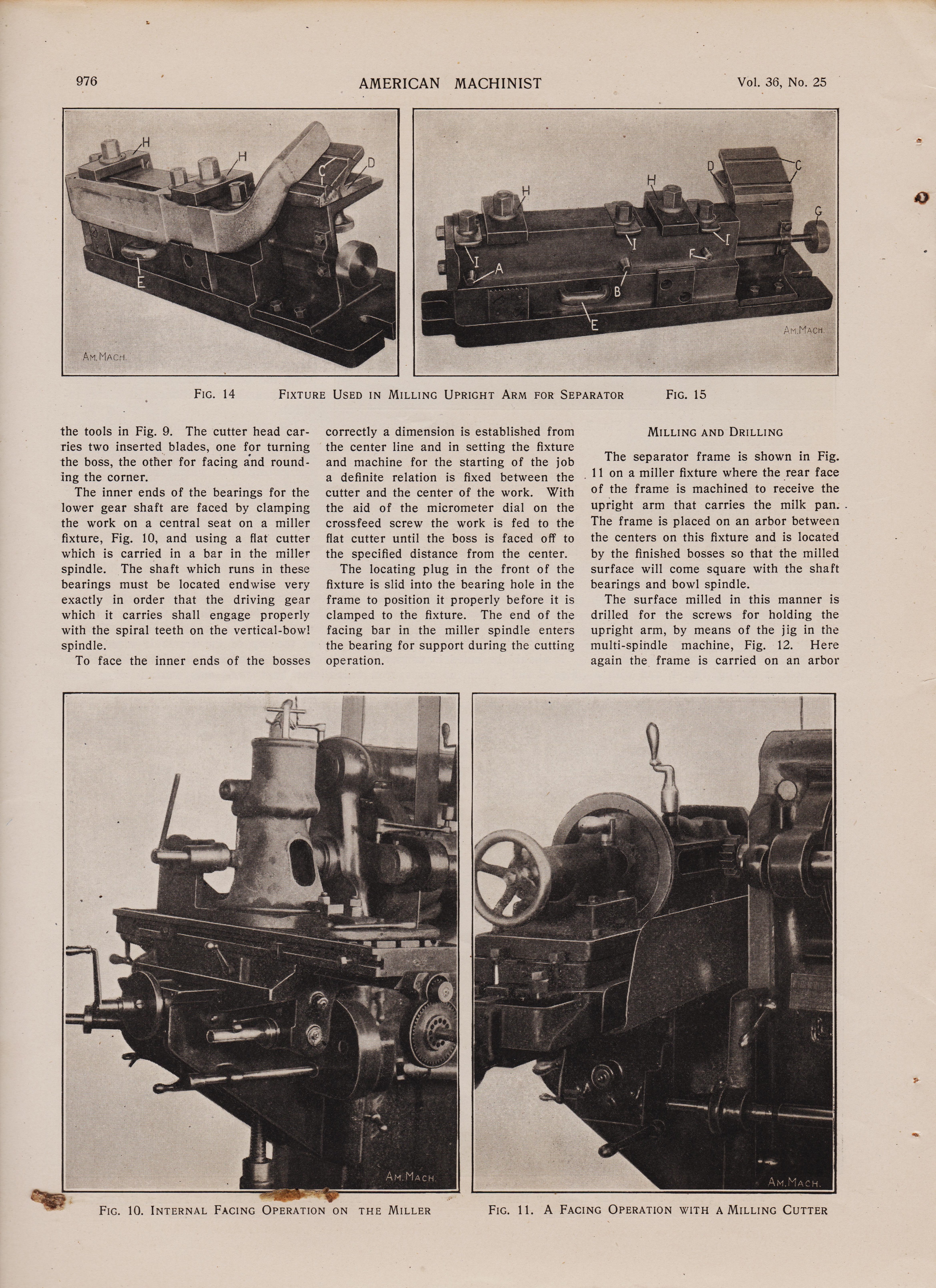
FIXTURE USED IN MILLING UPRIGHT ARM FOR SEPARATOR
FIG. 10. INTERNAL FACING OPERATION ON THE MILLER
FIG. 11. A FACING OPERATION WITH A MILLING CUTTER
FIG. 14 FIXTURE USED IN MILLING UPRIGHT ARM FOR SEPARATOR
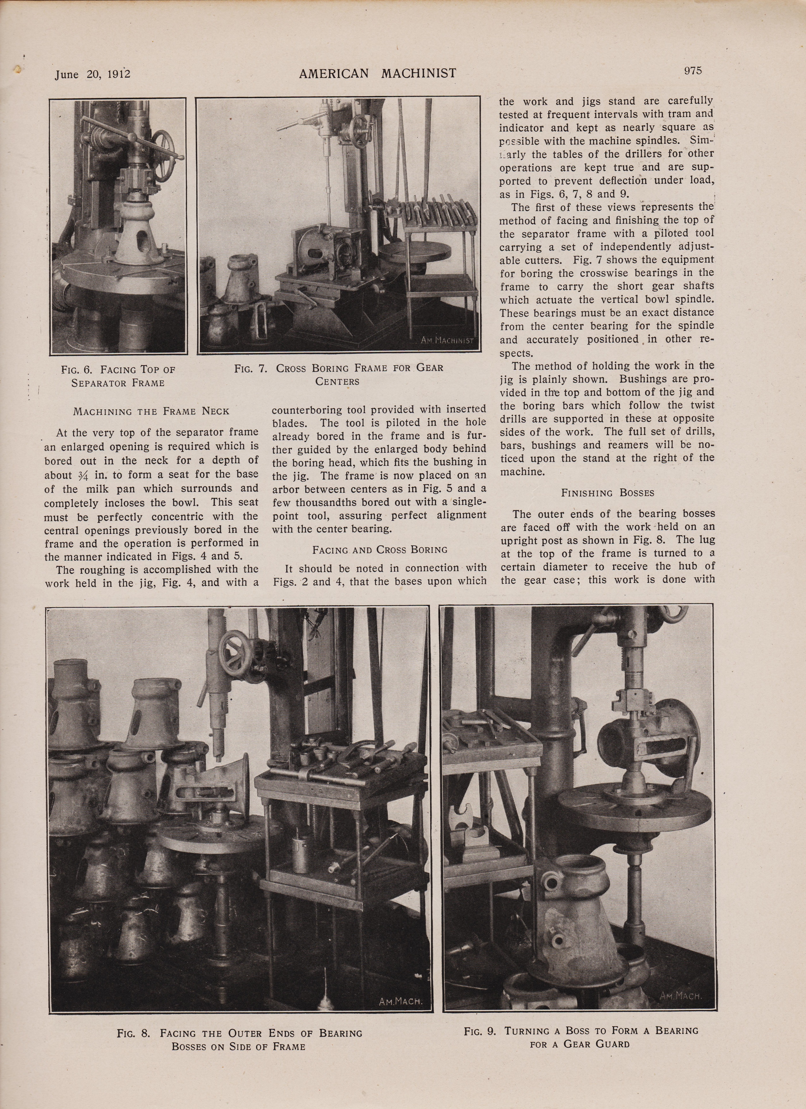
the tools in Fig. 9. The cutter head car-ries two inserted blades, one for turning the boss, the other for facing and round-ing the corner. The inner ends of the bearings for the lower gear shaft are faced by clamping the work on a central seat on a miller fixture, Fig. 10, and using a flat cutter which is carried in a bar in the miller spindle. The shaft which runs in these bearings must be located endwise very exactly in order that the driving gear which it carries shall engage properly with the spiral teeth on the vertical-bowl spindle. To face the inner ends of the bosses correctly a dimension is established from the center line and in setting the fixture and machine for the starting of the job a definite relation is fixed between the cutter and the center of the work. With the aid of the micrometer dial on the crossfeed screw the work is fed to the flat cutter until the boss is faced off to the specified distance from the center. The locating plug in the front of the fixture is slid into the bearing hole in the frame to position it properly before it is clamped to the fixture. The end of the facing bar in the miller spindle enters the bearing for support during the cutting operation.
FIG. 15 MILLING AND DRILLING
The separator frame is shown in Fig. 11 on a miller fixture where the rear face of the frame is machined to receive the upright arm that carries the milk pan.. The frame is placed on an arbor between the centers on this fixture and is located by the finished bosses so that the milled surface will come square with the shaft bearings and bowl spindle. The surface milled in this manner is drilled for the screws for holding the upright arm, by means of the jig in the multi-spindle machine, Fig. 12. Here again the frame is carried on an arbor FIG. 10. INTERNAL FACING OPERATION ON THE MILLER FIG. 11. A FACING OPERATION WITH A MILLING CUTTER
page 975 AMERICAN MACHINIST 1912
page 976 AMERICAN MACHINIST Vol. 36, No. 25
FIXTURE USED IN MILLING UPRIGHT ARM FOR SEPARATOR
FIG. 10. INTERNAL FACING OPERATION ON THE MILLER
FIG. 11. A FACING OPERATION WITH A MILLING CUTTER
FIG. 14 FIXTURE USED IN MILLING UPRIGHT ARM FOR SEPARATOR
the tools in Fig. 9. The cutter head car-ries two inserted blades, one for turning the boss, the other for facing and round-ing the corner. The inner ends of the bearings for the lower gear shaft are faced by clamping the work on a central seat on a miller fixture, Fig. 10, and using a flat cutter which is carried in a bar in the miller spindle. The shaft which runs in these bearings must be located endwise very exactly in order that the driving gear which it carries shall engage properly with the spiral teeth on the vertical-bowl spindle. To face the inner ends of the bosses correctly a dimension is established from the center line and in setting the fixture and machine for the starting of the job a definite relation is fixed between the cutter and the center of the work. With the aid of the micrometer dial on the crossfeed screw the work is fed to the flat cutter until the boss is faced off to the specified distance from the center. The locating plug in the front of the fixture is slid into the bearing hole in the frame to position it properly before it is clamped to the fixture. The end of the facing bar in the miller spindle enters the bearing for support during the cutting operation.
FIG. 15 MILLING AND DRILLING
The separator frame is shown in Fig. 11 on a miller fixture where the rear face of the frame is machined to receive the upright arm that carries the milk pan.. The frame is placed on an arbor between the centers on this fixture and is located by the finished bosses so that the milled surface will come square with the shaft bearings and bowl spindle. The surface milled in this manner is drilled for the screws for holding the upright arm, by means of the jig in the multi-spindle machine, Fig. 12. Here again the frame is carried on an arbor FIG. 10. INTERNAL FACING OPERATION ON THE MILLER FIG. 11. A FACING OPERATION WITH A MILLING CUTTER
AMERICAN MACHINIST
October 4, 1912.
p >Page 16-17
16 Buying—AMERICAN MACHINIST-Section Vol. 46, No.- 10
Exclusive Features of the Helical Gear Shaper
A MANUFACTURING MACHINE
taking advantage of the simplification and directness made possible by manufacturing design. A GENERATING CUTTER
ground to shape after hardening. All errors due to heat treatment and to hand-and-eye-copying processes are eliminated.
A HELIX MOTION
applied directly to the cutter spindle without complication, and without connection with the feed, index1ing or any other mechanism of the machine. It is not changed when changing the feed or number of teeth in the gear being cut.
A HELIX MOTION
that is at once direct, accurate, rigid and durable.
The HELIX ANGLE
is fixed and invariable. (there is a physical Adaptorplate added to the machine to rotate the cutter as it travels I have one The Webmaster) There is no possibility of error.
The gears shown are 7gears cut at one setting.
March 8, 1917 Buying—AMERICAN MACHINIST-Section pg 17
Right Off the Machine Ready to Run
There were no "ifs" about it, they simply had to have helical gears in the plant in which the gears shown on the opposite page are made. It seems, too, they had to run up against all sorts of trouble in cutting them. The gears never came off the machines they were formerly using accurate enough to be run without a lot of expensive fussing over them also with-out numerous rejections in assembling and testing.
Now, they use Helical Gear Shapers and their worries are ended—really ended. The gears cut on the Helical Gear Shaper come right off the machine ready for service. Give credit for this accuracy to the two outstanding features of the Helical Gear Shaper: First, the helix angle is absolutely fixed—Second, the helical cutter is ground after hardening.
We have a special Catalog on the Helical Gear Shaper which will be sent you on request. It gives the complete details of the machine and the method.
THE FELLOWS GEAR SHAPER CO. SPRINGFIELD, VERMONT, U. S. A.

AMERICAN MACHINIST
October 4, 1912. page 12
Selling--AMERICAN MACHINIST-Section Vol. 36, No. 25
Management How The Flat Turret Lathe
Line Between Excessive
The dividing line between excessive and insufficient stock must be drawn in each individual case. The amount of capital tied up in raw material, supplies, stock in process and finished product should not be greater than that which is necessary to get the greatest output per dollar of investment. There should be a constant supply of material throughout the entire work. The stock in process should flow through the plant in a rapid, thin stream, but with no greater quantity than absolutely necessary to insure a steady supply for all the workers, including assembling and selling workers. Yet, in spite of these true economic principles, there are many plants whose buildings and immense stock • carried represents three times the necessary investment. In these plants capital is often tied up in ways that actually throttle the output of the entire business. Furthermore, this is frequently done by increasing the portion of the investment that is irrevocably tied to the existing product, thus not only reducing the earning power of each dollar invested, but also increasing the hazard by tying the capital to the present product, which soon may be unsuited to the market demand. One of the most common errors in this respect is the one that regards the reduction of the labor cost as the paramount consideration. While the net cost per piece is natur-ally an important element it should neither eclipse the question of profit per dollar invested, nor the risk of the capital tied up. For what is the gain if the means for reduction of the net labor cost re- Jones & Lamson Machine Company
Profit Pront Draws The Proper Dividing And Insufficient Stock
produces the profit more than the saving in labor. The Flat Turret Lathe is the proper machine to use in building machinery for profit. It makes profit for you by getting out your work when it is wanted and as it is wanted. It gives volt the largest output per dollar of investment ; also a low cost of work and an accurate dupli-sati on . The complete story is told in a valu-able book of 253 pages, entitled "Machine Building for Profit and the Flat Turret Lathe." Write for Tour copy.
Jones & Lamson Machine Company
Springfield, Vermont, U. S. A., and 97 Queen Victoria Street, London Germany, Holland, Belgium, Switzerland and Austria-Hungary: M. Koyemann, Charlottenstrasse, 112, Dusseldorf, Germany. France and Spain : Ph. Bonvillain and E. Ronceray, 9 and 11, Rue des Envierges, Paris, France. Italy : Adler & Eisenschitz, Milan. Springfield, Vermont, U. S. A., and 97 Queen Victoria Street, London Germany, Holland, Belgium, Switzerland and Austria - Hungary: M. Koyemann, Charlottenstrasse, 112, Dusseldorf, Germany. France and Spain: Ph. Bonvillain and E. Ronceray, 9 and 11, Rue des Envierges, Paris, France. Italy: Adler & Eisenschitz, Milan.

Page 24, Selling--AMERICAN MACHINIST-Section Vol. 36, No. 25
"IDEAL" LATHES -----made in 14" 16" and 18" swing.
"IDEAL" LATHES
Can be furnished with Oil Pan, Oil Pump, Electric Motors, Re-lieving Attachment, Taper Attachment, Turret on Carriage or Bed, etc., etc. 14" "IDEAL" ENGINE LATHE WITH OIL. PAN
are equipped with Friction Geared Head, Rapid Change Gear Device (Patented), Automatic Stop, New Reverse Motion. "SIMPLY PERFECT"
We also manufacture full lines of STANDARD LATHES with 3 or 5 STEP CONES, sizes 14" to 42" swing, HIGH SPEED LATHES, BRASS FINISHING LATHES, CRANK AND GEARED SHAPERS, Etc.
THE SPRINGFIELD MACHINE TOOL CO. SPRINGFIELD, OHIO
Agent for Chicago: The E. L. Essley Machinery Co. Neil Machinery Co., Cleveland, Ohio. The Coghlin Machinery & Supply Co., Toledo, Ohio. Los Angeles Machinery & Supply Co., Los. Angeles, Cal. Italy: Stussi & Zweifel, Milan. Germany: Ludw. Loewe & Co., Berlin. France: Alfred Herbert, Paris. ***********************************************************************************
A Blanchard Belt DriveSurface Grinder
High-Power Vertical Surface Grinder
will often save expensive scraping and lapping operations. Flat Valves, 12" x 10", require from 2 to 3 hours of scraping to bring the sides flat and parallel. The BLANCHARD finishes 6 valves per hour on both sides. No finish planing is required. Investigate the BLA NC HARD for your work,
The Blanchard Machine Co. 64 State St., Cambridge "A," Mass.
AGENTS-Prentiss Tool & Supply Co., Motch & Merryweather Mach'y Co., Marshall & Husehart Mach'y Co., Kemp Mach'y Co., W. E. Shipley Mach'y Co., Williams & Wilson, C. W. Burton, Griffiths & Co., Alfred H. Schutte, Schuchardt & Schutte.
The end of the Cream
i str half DP pic
"IDEAL" LATHES -----made in 14" 16" and 18" swing.
"IDEAL" LATHES
Can be furnished with Oil Pan, Oil Pump, Electric Motors, Re-lieving Attachment, Taper Attachment, Turret on Carriage or Bed, etc., etc. 14" "IDEAL" ENGINE LATHE WITH OIL. PAN
are equipped with Friction Geared Head, Rapid Change Gear Device (Patented), Automatic Stop, New Reverse Motion. "SIMPLY PERFECT"
We also manufacture full lines of STANDARD LATHES with 3 or 5 STEP CONES, sizes 14" to 42" swing, HIGH SPEED LATHES, BRASS FINISHING LATHES, CRANK AND GEARED SHAPERS, Etc.
THE SPRINGFIELD MACHINE TOOL CO. SPRINGFIELD, OHIO
Agent for Chicago: The E. L. Essley Machinery Co. Neil Machinery Co., Cleveland, Ohio. The Coghlin Machinery & Supply Co., Toledo, Ohio. Los Angeles Machinery & Supply Co., Los. Angeles, Cal. Italy: Stussi & Zweifel, Milan. Germany: Ludw. Loewe & Co., Berlin. France: Alfred Herbert, Paris. ***********************************************************************************
A Blanchard Belt DriveSurface Grinder
High-Power Vertical Surface Grinder
will often save expensive scraping and lapping operations. Flat Valves, 12" x 10", require from 2 to 3 hours of scraping to bring the sides flat and parallel. The BLANCHARD finishes 6 valves per hour on both sides. No finish planing is required. Investigate the BLA NC HARD for your work,
The Blanchard Machine Co. 64 State St., Cambridge "A," Mass.
AGENTS-Prentiss Tool & Supply Co., Motch & Merryweather Mach'y Co., Marshall & Husehart Mach'y Co., Kemp Mach'y Co., W. E. Shipley Mach'y Co., Williams & Wilson, C. W. Burton, Griffiths & Co., Alfred H. Schutte, Schuchardt & Schutte.
Buying-AMERICAN MACHINIST-Section Vol. 46, No. 10
June 20, 1912 Selling—AMERICAN MACHINIST—Section 25
Chucking Work Turned Out 1"r7,* 3 to 5 Times Faster than Ordinarily
THE New Britian Machine CO NEW BRITAIN CONN
The Logical Way
to handle chuck work, irregular-shaped forgings and castings and second rod work operations, whether such work requires machining at one or both ends, is to place the pieces in a New Britain Automatic. This is the logical method, because it assures a 3 to 5 times greater output at lower cost, with cheaper labor and with a worth-while saving in steps and unnecessary machinery. Consider these features. Apply their value to your own particular chucking proposition.
1. No hand work other than to load and unload the multiple chuck turret, which has one more chucking posi-tion than there are spindle positions. 2. The ability of the machine to finish a piece in the period of time taken to perform the longest single operation. 3. An accu-rately finished product, always. 4. The elimination of different types of machines. We're ready to submit production figures based on your samples.
82 Per Hour
This Malleable Iron 11" Union Nut is finished at one setting on the New Britain No. 24 Four-Spindle Single-Head Automatic Turret Machine. Chamfered for thread. Bored in two diameters and tapped. Basis of production—Spindle Speed, 70 r. p. m. Cutting Speed, 45 feet per minute. Cutting Feed, 40 turns per inch. Total operator's time per 100 pieces, 73 minutes. The New Britain Machine Company, 20 Chestnut Street New Britain, Conn.
FOREIGN AGENTS—Alfred H. Schutte, Cologne, Brussels, Milan, Bilbao, Berlin and Paris: Schuchardt & Schutte, London and St. Petersburg.
the end of cream
https://antiquemachinery.com/images-2021/1912-American-Machinist-Magazine-1912-June-30-pg-6-Cincinnati-Milling-Machine-Horizontal.jpeg
i str half DP pic
June 20, 1912 Selling—AMERICAN MACHINIST—Section 25
Chucking Work Turned Out 1"r7,* 3 to 5 Times Faster than Ordinarily
THE New Britian Machine CO NEW BRITAIN CONN
The Logical Way
to handle chuck work, irregular-shaped forgings and castings and second rod work operations, whether such work requires machining at one or both ends, is to place the pieces in a New Britain Automatic. This is the logical method, because it assures a 3 to 5 times greater output at lower cost, with cheaper labor and with a worth-while saving in steps and unnecessary machinery. Consider these features. Apply their value to your own particular chucking proposition.
1. No hand work other than to load and unload the multiple chuck turret, which has one more chucking posi-tion than there are spindle positions. 2. The ability of the machine to finish a piece in the period of time taken to perform the longest single operation. 3. An accu-rately finished product, always. 4. The elimination of different types of machines. We're ready to submit production figures based on your samples.
82 Per Hour
This Malleable Iron 11" Union Nut is finished at one setting on the New Britain No. 24 Four-Spindle Single-Head Automatic Turret Machine. Chamfered for thread. Bored in two diameters and tapped. Basis of production—Spindle Speed, 70 r. p. m. Cutting Speed, 45 feet per minute. Cutting Feed, 40 turns per inch. Total operator's time per 100 pieces, 73 minutes. The New Britain Machine Company, 20 Chestnut Street New Britain, Conn.
FOREIGN AGENTS—Alfred H. Schutte, Cologne, Brussels, Milan, Bilbao, Berlin and Paris: Schuchardt & Schutte, London and St. Petersburg.

June 20, 1912 Selling--AMERICAN MACHINIST--Section 163
Investigate Hendey Lincoln Millers Before Installing Special Machinery
The number of special machines re-quired in shops where one or more Hendey Lincoln Millers are installed is surprisingly small. Many operations which don't seem to fit your present equipment can be handled easily and quickly by our various types of Lincoln Millers. In addition to performing the un-usual jobs the "Hendey Lincolns" fill in with your regular run of work. So you see, they keep your invested capital producing all the time. Types and Sizes For Light and Heavy Work
The designs of "Hendy Types" cover an important advance Lincoln Miller Construction in that they have been given sufficient weight and working capacity to make them available for heavy- manufacturing which has never been touched by other types of Lincoln Millers. Many automobile manufacturers are find-ing our No. 8 Double Head Machine particularly adaptable to automobile engine work in quantity productions. An impor-tant feature is the greater rigidity secured by the direct method of supporting table on bed of machine, allowing heavier cuts at high speed. It will be worth while to have our catalogs for reference. Send in your request now.
The Hendey Machine Company Torrington, Conn., U. S. A.
Manning, Maxwell & Moore, Chicago, New York, Boston, Philadelphia, Pittsburg, Syracuse, Detroit, St. Louis, Milwaukee. The A. R. Williams Machinery Co.,-Toi onto, Ontario. Williams & Wilson, Montreal. General Supply Co.' of Canada, Ottawa, Ontario. C. W. Burton,Priffiths & Co., London. Alfred Herbert, Ltd., Paris. Ing. Ercole Vaghi, Milan, Italy. Schuchardt & Schutte, Berlin, Vienna, St. Petersburg, Stockholm.
i str half DP pic
Investigate Hendey Lincoln Millers Before Installing Special Machinery
The number of special machines re-quired in shops where one or more Hendey Lincoln Millers are installed is surprisingly small. Many operations which don't seem to fit your present equipment can be handled easily and quickly by our various types of Lincoln Millers. In addition to performing the un-usual jobs the "Hendey Lincolns" fill in with your regular run of work. So you see, they keep your invested capital producing all the time. Types and Sizes For Light and Heavy Work
The designs of "Hendy Types" cover an important advance Lincoln Miller Construction in that they have been given sufficient weight and working capacity to make them available for heavy- manufacturing which has never been touched by other types of Lincoln Millers. Many automobile manufacturers are find-ing our No. 8 Double Head Machine particularly adaptable to automobile engine work in quantity productions. An impor-tant feature is the greater rigidity secured by the direct method of supporting table on bed of machine, allowing heavier cuts at high speed. It will be worth while to have our catalogs for reference. Send in your request now.
The Hendey Machine Company Torrington, Conn., U. S. A.
Manning, Maxwell & Moore, Chicago, New York, Boston, Philadelphia, Pittsburg, Syracuse, Detroit, St. Louis, Milwaukee. The A. R. Williams Machinery Co.,-Toi onto, Ontario. Williams & Wilson, Montreal. General Supply Co.' of Canada, Ottawa, Ontario. C. W. Burton,Priffiths & Co., London. Alfred Herbert, Ltd., Paris. Ing. Ercole Vaghi, Milan, Italy. Schuchardt & Schutte, Berlin, Vienna, St. Petersburg, Stockholm.

page 8 (NOTE: look at the picture of the early old fashened Flat Twisted Drill still used in the Radial)
Selling--AMERICAN MACHINIST--Section Vol. 36, No. 25
HERE'S PROOF
of the satisfactory service that "American" Radial Drills are giving
JET 6140 SURFACE CONDENSER St
WE ARE NOT IN THE PUMP TRUST
DEAN BROTHERS STEAM PUMP WORKS INDIANAPOLIS, (ND.
American Tool Works Co , Cincinnati, Ohio
July 10, 1911.
Gentlemen:-We have made a thorough test of your six foot radial drill and wish to express our satisfaction, It exceeds your guarantee We herewith enclose photo of the drill at work. .In the foreground are the borings from five hours work. The drill in use is a three inch twist drill in solid steel no relief drill is used Yours truly,
DE BROS. STEAM PUMP WKS. By JCD/CtA
The Originals of the above letter and photograph were sent us Voluntarily, without any request from us, by the Dean Bros. Steam Pump Works, Indianapolis, Ind.
From similar letters which we have received we know that "American" Radials are giving practically Universal Satisfaction. Let us send you Circular No. 358 D Which explains all the Superior Features of these Radial Drills. The American Tool Works Co., Cincinnati, U.S.A. Lathes Planers Shapers Radials
i str half DP pic
Selling--AMERICAN MACHINIST--Section Vol. 36, No. 25
HERE'S PROOF
of the satisfactory service that "American" Radial Drills are giving
JET 6140 SURFACE CONDENSER St
WE ARE NOT IN THE PUMP TRUST
DEAN BROTHERS STEAM PUMP WORKS INDIANAPOLIS, (ND.
American Tool Works Co , Cincinnati, Ohio
July 10, 1911.
Gentlemen:-We have made a thorough test of your six foot radial drill and wish to express our satisfaction, It exceeds your guarantee We herewith enclose photo of the drill at work. .In the foreground are the borings from five hours work. The drill in use is a three inch twist drill in solid steel no relief drill is used Yours truly,
DE BROS. STEAM PUMP WKS. By JCD/CtA
The Originals of the above letter and photograph were sent us Voluntarily, without any request from us, by the Dean Bros. Steam Pump Works, Indianapolis, Ind.
From similar letters which we have received we know that "American" Radials are giving practically Universal Satisfaction. Let us send you Circular No. 358 D Which explains all the Superior Features of these Radial Drills. The American Tool Works Co., Cincinnati, U.S.A. Lathes Planers Shapers Radials

page 25
June 20, 1912 Selling—AMERICAN MACHINIST—Section 25
Chucking Work Turned Out 1 to 7 3 to 5 Times Faster than Ordinarily.
The New Britan Automatic Lathe Screw Machine CO, NEW BRITAIN CONN„
The Logical Way
to handle chuck work, irregular-shaped forgings and castings and second rod work operations, whether such work requires machining at one or both ends, is to place the pieces in a New Britain Automatic. This is the logical method, because it assures a 3 to 5 times greater output at lower cost, with cheaper labor and with a worth-while saving in steps and unnecessary machinery. Consider these features. Apply their value to your own particular chucking proposition.
1. No hand work other than to load and unload the multiple chuck turret, which has one more chucking posi-tion than there are spindle positions.
2. The ability of the machine to finish a piece in the period of time taken to perform the longest single operation.
3. An accurately finished product, always.
4. The elimination of different types of machines. We're ready to submit production figures based on your samples.
82 Per Hour
This Malleable Iron 11" Union Nut is finished at one setting on the New Britain No. 24 Four-Spindle Single-Head Automatic Turret Machine. Chamfered for thread. Bored in two diameters and tapped. Basis of production—Spindle Speed, 70 r. p. m. Cutting Speed, 45 feet per minute. Cutting Feed, 40 turns per inch. Total operator's time per 100 pieces, 73 minutes. The New Britain Machine Company 20 Chestnut Street New Britain, Conn.
FOREIGN AGENTS—Alfred H. Schutte, Cologne, Brussels, Milan, Bilbao, Berlin and Paris: Schuchardt & Schutte, London and St. Petersburg.
i str half DP pic
June 20, 1912 Selling—AMERICAN MACHINIST—Section 25
Chucking Work Turned Out 1 to 7 3 to 5 Times Faster than Ordinarily.
The New Britan Automatic Lathe Screw Machine CO, NEW BRITAIN CONN„
The Logical Way
to handle chuck work, irregular-shaped forgings and castings and second rod work operations, whether such work requires machining at one or both ends, is to place the pieces in a New Britain Automatic. This is the logical method, because it assures a 3 to 5 times greater output at lower cost, with cheaper labor and with a worth-while saving in steps and unnecessary machinery. Consider these features. Apply their value to your own particular chucking proposition.
1. No hand work other than to load and unload the multiple chuck turret, which has one more chucking posi-tion than there are spindle positions.
2. The ability of the machine to finish a piece in the period of time taken to perform the longest single operation.
3. An accurately finished product, always.
4. The elimination of different types of machines. We're ready to submit production figures based on your samples.
82 Per Hour
This Malleable Iron 11" Union Nut is finished at one setting on the New Britain No. 24 Four-Spindle Single-Head Automatic Turret Machine. Chamfered for thread. Bored in two diameters and tapped. Basis of production—Spindle Speed, 70 r. p. m. Cutting Speed, 45 feet per minute. Cutting Feed, 40 turns per inch. Total operator's time per 100 pieces, 73 minutes. The New Britain Machine Company 20 Chestnut Street New Britain, Conn.
FOREIGN AGENTS—Alfred H. Schutte, Cologne, Brussels, Milan, Bilbao, Berlin and Paris: Schuchardt & Schutte, London and St. Petersburg.
page 62
Selling--AMERICAN MACHINIST--Section Vol. 36, No. 25 Designed, Built and Tested Like A Steam Engine
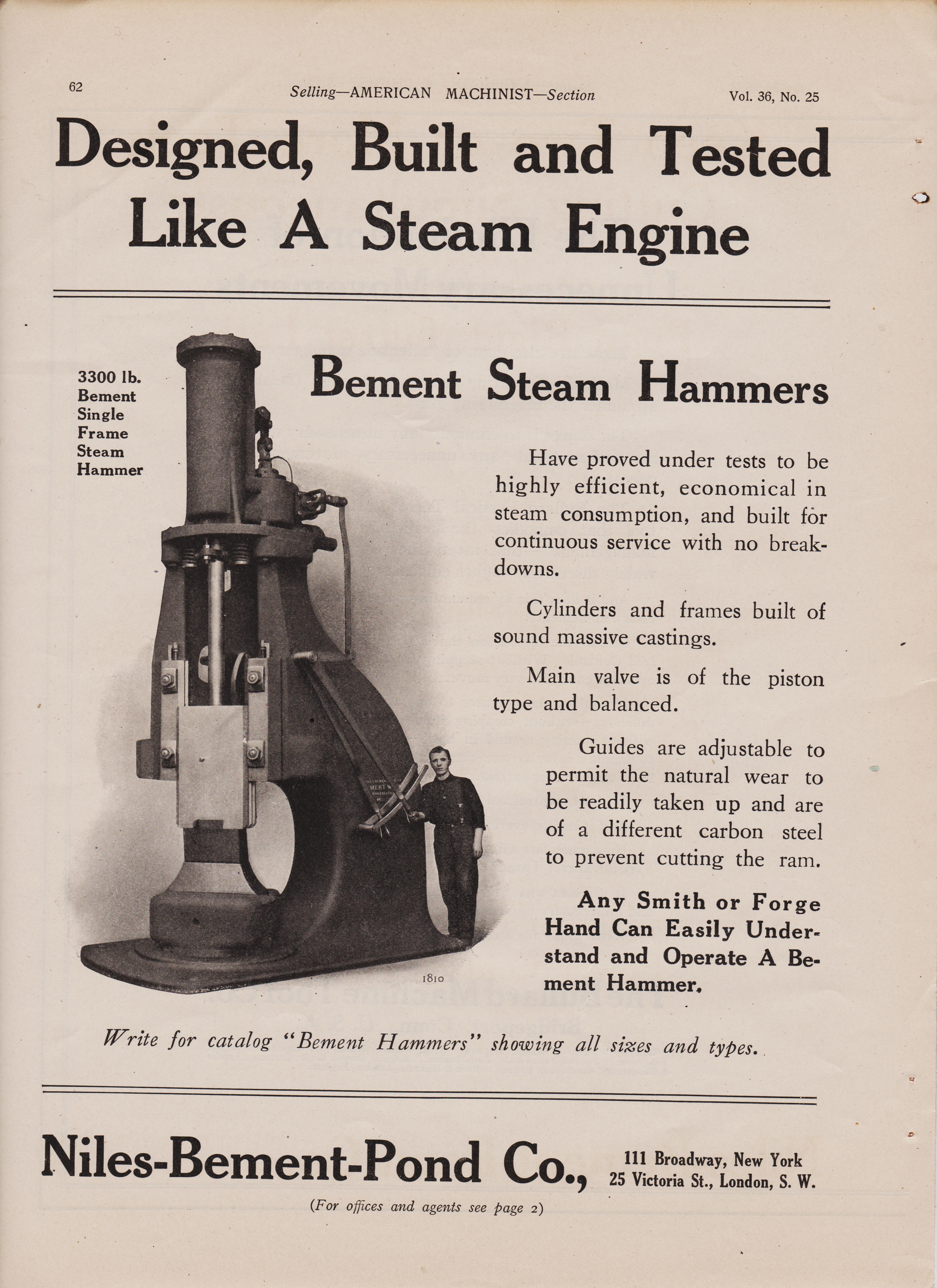
3300 lb. Bement Single Frame Steam Hammer
Bement Steam Hammers
Have proved under tests to be highly efficient, economical in steam consumption, and built for continuous service with no break-downs. Cylinders and frames built of sound massive castings. Main valve is of the piston type and balanced. Guides are adjustable to permit the natural wear to be readily taken up and are of a different carbon steel to prevent cutting the ram. Any Smith or Forge Hand Can Easily Under-stand and Operate A Bement Hammer, 1810
Write for catalog "Bement Hammers" showing all sizes and types..
Niles-Bement-Pond Co., 2511V1i:orroiaadZyLonedwon,YoSr.W. (For offices and agents see page 2)
i str half DP pic
Selling--AMERICAN MACHINIST--Section Vol. 36, No. 25 Designed, Built and Tested Like A Steam Engine
3300 lb. Bement Single Frame Steam Hammer
Bement Steam Hammers
Have proved under tests to be highly efficient, economical in steam consumption, and built for continuous service with no break-downs. Cylinders and frames built of sound massive castings. Main valve is of the piston type and balanced. Guides are adjustable to permit the natural wear to be readily taken up and are of a different carbon steel to prevent cutting the ram. Any Smith or Forge Hand Can Easily Under-stand and Operate A Bement Hammer, 1810
Write for catalog "Bement Hammers" showing all sizes and types..
Niles-Bement-Pond Co., 2511V1i:orroiaadZyLonedwon,YoSr.W. (For offices and agents see page 2)
>
June 20, 1912
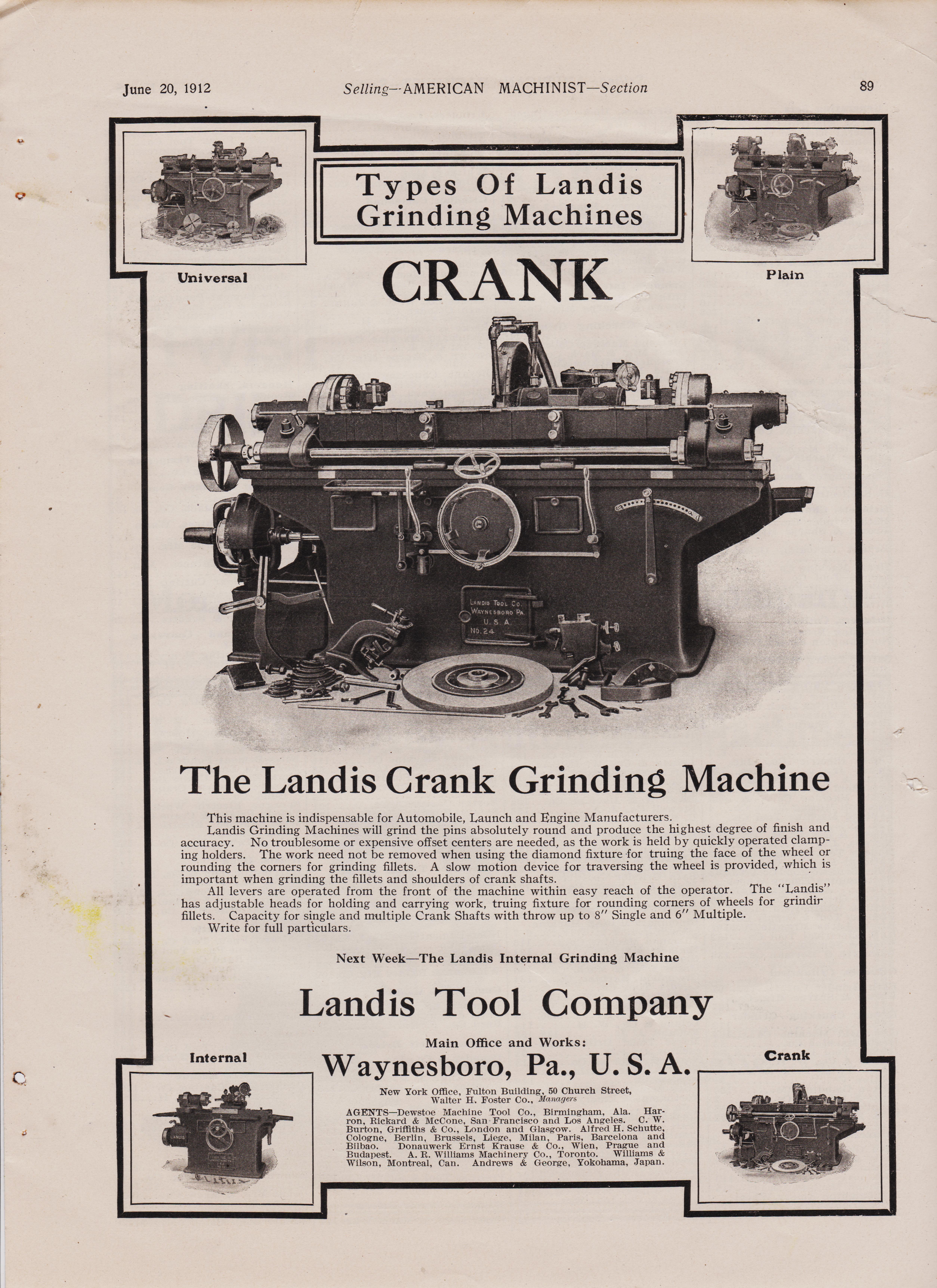
Selling--AMERICAN MACHINIST--Section Types Of Landis Grinding Machines
Universal CRANK GRINDER page 89
The Landis Crank Grinding Machine
This machine is indispensable for Automobile, Launch and Engine Manufacturers.
Landis Grinding Machines will grind the pins absolutely round and produce the highest degree of finish and accuracy.
No troublesome or expensive offset centers are needed, as the work is held by quickly operated clamping holders.
The work need not be removed when using the diamond fixture for truing the face of the wheel or rounding the corners for grinding fillets.
A slow motion device for traversing the wheel is provided, which is important when grinding the fillets and shoulders of crank shafts.
All levers are operated from the front of the machine within easy reach of the operator.
The Landis has adjustable heads for holding and carrying work, truing fixture for rounding corners of wheels for grinding fillets.
Capacity for single and multiple Crank Shafts with throw up to 8" Single and 6" Multiple. Write for full particulars.
Next Week----The Landis Internal Grinding Machine Landis Tool Company Internal
Main Office and Works: Waynesboro, Pa., U. S. A.
New York Office, Fulton Building, 50 Church Street, Walter H. Foster Co., Manager, AGENTS-Dewstoe Machine Tool Co., Birmingham, Ala. Harron, Rickard & McCone, San Francisco and Los Angeles. C. W. Burton, Griffiths & Co., London and Glasgow. Alfred H. Schutte, Cologne, Berlin, Brussels, Liege, Milan, Paris, Barcelona and Bilbao. Donauwerk Ernst Krause & Co., Wien, Prague and Budapest. A. R. Williams Machinery Co., Toronto. Williams & Wilson, Montreal, Can. Andrews & George, Yokohama, Japan. Crank
i str half DP pic
Selling--AMERICAN MACHINIST--Section Types Of Landis Grinding Machines
Universal CRANK GRINDER page 89
The Landis Crank Grinding Machine
This machine is indispensable for Automobile, Launch and Engine Manufacturers.
Landis Grinding Machines will grind the pins absolutely round and produce the highest degree of finish and accuracy.
No troublesome or expensive offset centers are needed, as the work is held by quickly operated clamping holders.
The work need not be removed when using the diamond fixture for truing the face of the wheel or rounding the corners for grinding fillets.
A slow motion device for traversing the wheel is provided, which is important when grinding the fillets and shoulders of crank shafts.
All levers are operated from the front of the machine within easy reach of the operator.
The Landis has adjustable heads for holding and carrying work, truing fixture for rounding corners of wheels for grinding fillets.
Capacity for single and multiple Crank Shafts with throw up to 8" Single and 6" Multiple. Write for full particulars.
Next Week----The Landis Internal Grinding Machine Landis Tool Company Internal
Main Office and Works: Waynesboro, Pa., U. S. A.
New York Office, Fulton Building, 50 Church Street, Walter H. Foster Co., Manager, AGENTS-Dewstoe Machine Tool Co., Birmingham, Ala. Harron, Rickard & McCone, San Francisco and Los Angeles. C. W. Burton, Griffiths & Co., London and Glasgow. Alfred H. Schutte, Cologne, Berlin, Brussels, Liege, Milan, Paris, Barcelona and Bilbao. Donauwerk Ernst Krause & Co., Wien, Prague and Budapest. A. R. Williams Machinery Co., Toronto. Williams & Wilson, Montreal, Can. Andrews & George, Yokohama, Japan. Crank

June 20, 1912
Selling--AMERICAN MACHINIST--Section
page 29
Time Saving Features In The Prentice Radial Built By Prentice Bros. Co., Worcester, Mass.
4' Arm Radial Pulling an 8" Pipe Tap—Ball-bearing throughout.
THE EASE AND FACILITY of positioning the arm and spindle, the roller clutch permitting hand feed ahead of engaged power feed—which alone enables an average saving of thirty seconds in the starting of every hole—the dial depth gauge, the automatic stop motion and the five-to-one quick return of the spindle are among the time saving features.
NEW YORK OFFICES3 HUDSON TERM. INAL BUILDING 30 CHURCH ST. EASTERN WAREHOUSES: JERSEY CITY BOONTON° N.J. ESTABLISHED 1842 INCORPORATED 1888 JOSEPH T. RYERSON & SON CLYDE M. CARR, PRESIDENT JOSEPH T. RYERSON, VICE•PRES4 MACHINERY CHICAG0 PITTS B URG CLEVELAND MILWAUKEE ST. LOUIS KANSAS CITY MINNEAPOLIS HOUSTON SEATTLE DETROIT SELLING AGENTS: ..THE H.V. LEWIS COMPANY, NEW YORK AND PHILADELPHIA. THE FAIRBANKS COMPANY, BOSTON. BALTIMORE, BUIFFAline !,ARTFORD AND PITTSBURG. THE BROWNELL MACHINERY COMPANY, PROVIDENCE, R. 1. THE C. H. WOOD COMPANY. S'/RACUSE, N. Y. SCHUCHAR DT A SCHUTTE, LONDON, BERLIN, ST. PETERSBURG, VIENNA, BUDAPEST, STOCKHOLM AND COPENHAGEN. THE ALLIED MACHINERY COMPANY OF AMERICA. PARIS
fair https://antiquemachinery.com/images-2021/1912-American-Machinist-Magazine-1912-June-30-pg-4-Ingersoll-Milling-Machine-Co-Large-Milling-Cutters.jpeg
not so good https://antiquemachinery.com/images-2021/1912-American-Machinist-Magazine-1912-June-30-pg-125-Pratt-and-Whitney-Co-Taps-small-tools.jpg
https://antiquemachinery.com/images-2021/1912-American-Machinist-Magazine-1912-June-pg-36-F-E-Reed-Co-Cone-head-Engine-Lathe.jpeg
i str half DP pic
page 29
Time Saving Features In The Prentice Radial Built By Prentice Bros. Co., Worcester, Mass.
4' Arm Radial Pulling an 8" Pipe Tap—Ball-bearing throughout.
THE EASE AND FACILITY of positioning the arm and spindle, the roller clutch permitting hand feed ahead of engaged power feed—which alone enables an average saving of thirty seconds in the starting of every hole—the dial depth gauge, the automatic stop motion and the five-to-one quick return of the spindle are among the time saving features.
NEW YORK OFFICES3 HUDSON TERM. INAL BUILDING 30 CHURCH ST. EASTERN WAREHOUSES: JERSEY CITY BOONTON° N.J. ESTABLISHED 1842 INCORPORATED 1888 JOSEPH T. RYERSON & SON CLYDE M. CARR, PRESIDENT JOSEPH T. RYERSON, VICE•PRES4 MACHINERY CHICAG0 PITTS B URG CLEVELAND MILWAUKEE ST. LOUIS KANSAS CITY MINNEAPOLIS HOUSTON SEATTLE DETROIT SELLING AGENTS: ..THE H.V. LEWIS COMPANY, NEW YORK AND PHILADELPHIA. THE FAIRBANKS COMPANY, BOSTON. BALTIMORE, BUIFFAline !,ARTFORD AND PITTSBURG. THE BROWNELL MACHINERY COMPANY, PROVIDENCE, R. 1. THE C. H. WOOD COMPANY. S'/RACUSE, N. Y. SCHUCHAR DT A SCHUTTE, LONDON, BERLIN, ST. PETERSBURG, VIENNA, BUDAPEST, STOCKHOLM AND COPENHAGEN. THE ALLIED MACHINERY COMPANY OF AMERICA. PARIS
page 36
Selling--AMERICAN MACHINIST--Section Vol. 36, No. 25
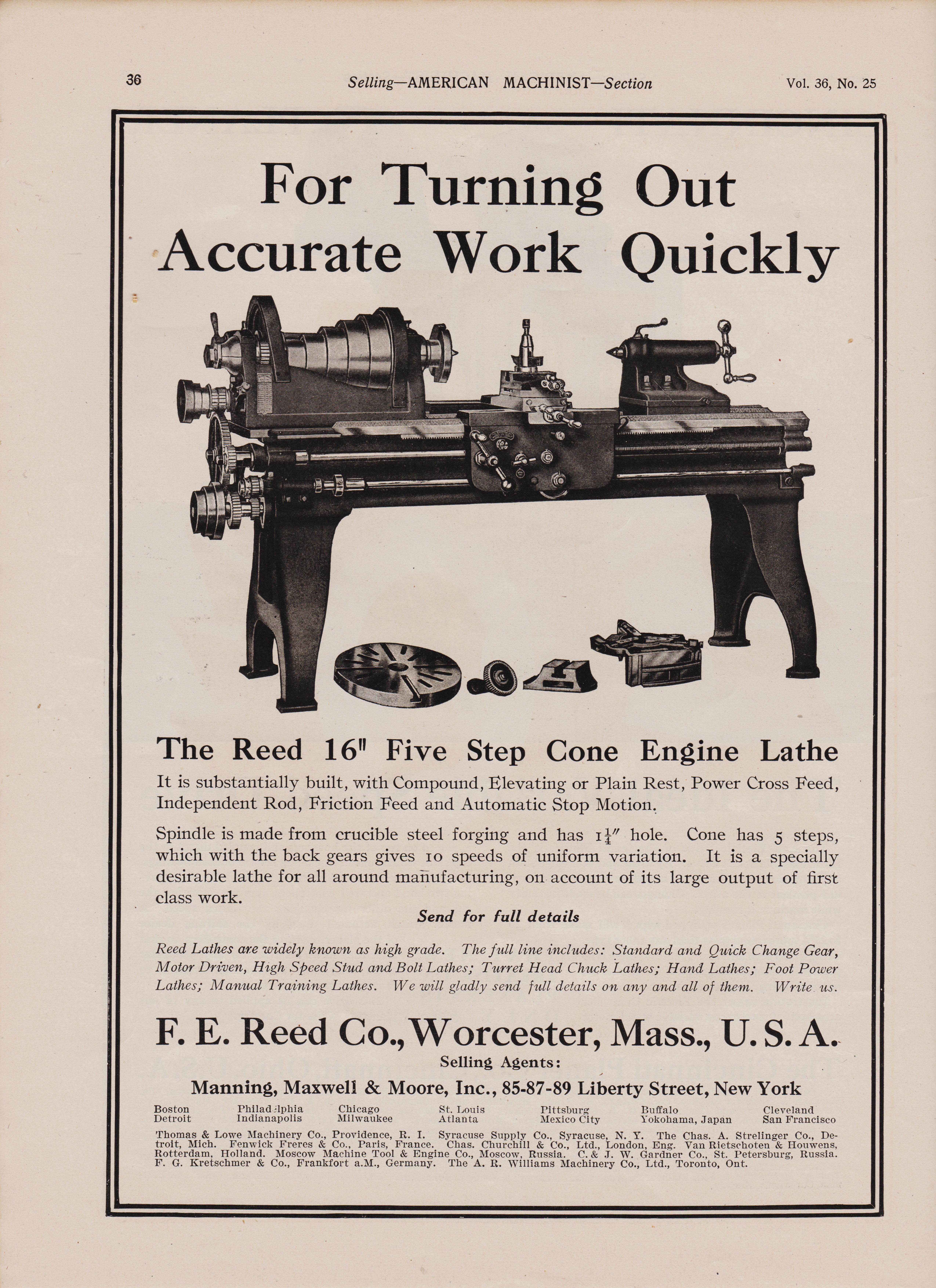
For Turning Out Accurate Work Quickly
The Reed 16" Five Step Cone Engine Lathe It is substantially built, with Compound, Elevating or Plain Rest, Power Cross Feed, Independent Rod, Friction Feed and Automatic Stop Motion. Spindle is made from crucible steel forging and has z 1" hole. Cone has 5 steps, which with the back gears gives io speeds of uniform variation. It is a specially desirable lathe for all around manufacturing, on account of its large output of first class work. Send for full details
Reed Lathes are widely known as high grade. The full line includes: Standard and Quick Change Gear, Motor Driven, High Speed Stud and Bolt Lathes; Turret Head Chuck Lathes; Hand Lathes; Foot Power Lathes; Manual Training Lathes. We will gladly send full details on any and all of them. Write, us.
F. E. Reed Co., Worcester, Mass., U. S. A.
Selling Agents: Manning, Maxwell & Moore, Inc., 85-87-89 Liberty Street, New York Boston Philadelphia Chicago St. Louis Detroit Indianapolis Milwaukee Atlanta Pittsburg Mexico City Buffalo Cleveland Yokohama, Japan San Francisco Thomas & Lowe Machinery Co., Providence, R. I. Syracuse Supply Co.' Syracuse, N. Y. The Chas. A. Strelinger Co., De-troit, Mich. Fenwick Freres & Co., Paris, France. Chas. Churchill & Co., Ltd., London, Eng. Van Rietschoten & Houwens, Rotterdam, Holland. Moscow Machine Tool & Engine Co., Moscow, Russia. C. & J. W. Gardner Co., St. Petersburg, Russia. F. G. Kretschmer & Co., Frankfort a.M., Germany. The A. R. Williams Machinery Co., Ltd., Toronto, Ont.
reed pic
Selling--AMERICAN MACHINIST--Section Vol. 36, No. 25
For Turning Out Accurate Work Quickly
The Reed 16" Five Step Cone Engine Lathe It is substantially built, with Compound, Elevating or Plain Rest, Power Cross Feed, Independent Rod, Friction Feed and Automatic Stop Motion. Spindle is made from crucible steel forging and has z 1" hole. Cone has 5 steps, which with the back gears gives io speeds of uniform variation. It is a specially desirable lathe for all around manufacturing, on account of its large output of first class work. Send for full details
Reed Lathes are widely known as high grade. The full line includes: Standard and Quick Change Gear, Motor Driven, High Speed Stud and Bolt Lathes; Turret Head Chuck Lathes; Hand Lathes; Foot Power Lathes; Manual Training Lathes. We will gladly send full details on any and all of them. Write, us.
F. E. Reed Co., Worcester, Mass., U. S. A.
Selling Agents: Manning, Maxwell & Moore, Inc., 85-87-89 Liberty Street, New York Boston Philadelphia Chicago St. Louis Detroit Indianapolis Milwaukee Atlanta Pittsburg Mexico City Buffalo Cleveland Yokohama, Japan San Francisco Thomas & Lowe Machinery Co., Providence, R. I. Syracuse Supply Co.' Syracuse, N. Y. The Chas. A. Strelinger Co., De-troit, Mich. Fenwick Freres & Co., Paris, France. Chas. Churchill & Co., Ltd., London, Eng. Van Rietschoten & Houwens, Rotterdam, Holland. Moscow Machine Tool & Engine Co., Moscow, Russia. C. & J. W. Gardner Co., St. Petersburg, Russia. F. G. Kretschmer & Co., Frankfort a.M., Germany. The A. R. Williams Machinery Co., Ltd., Toronto, Ont.
page 48
Selling--AMERICAN MACHINIST--Section Vol. 36, No. 25
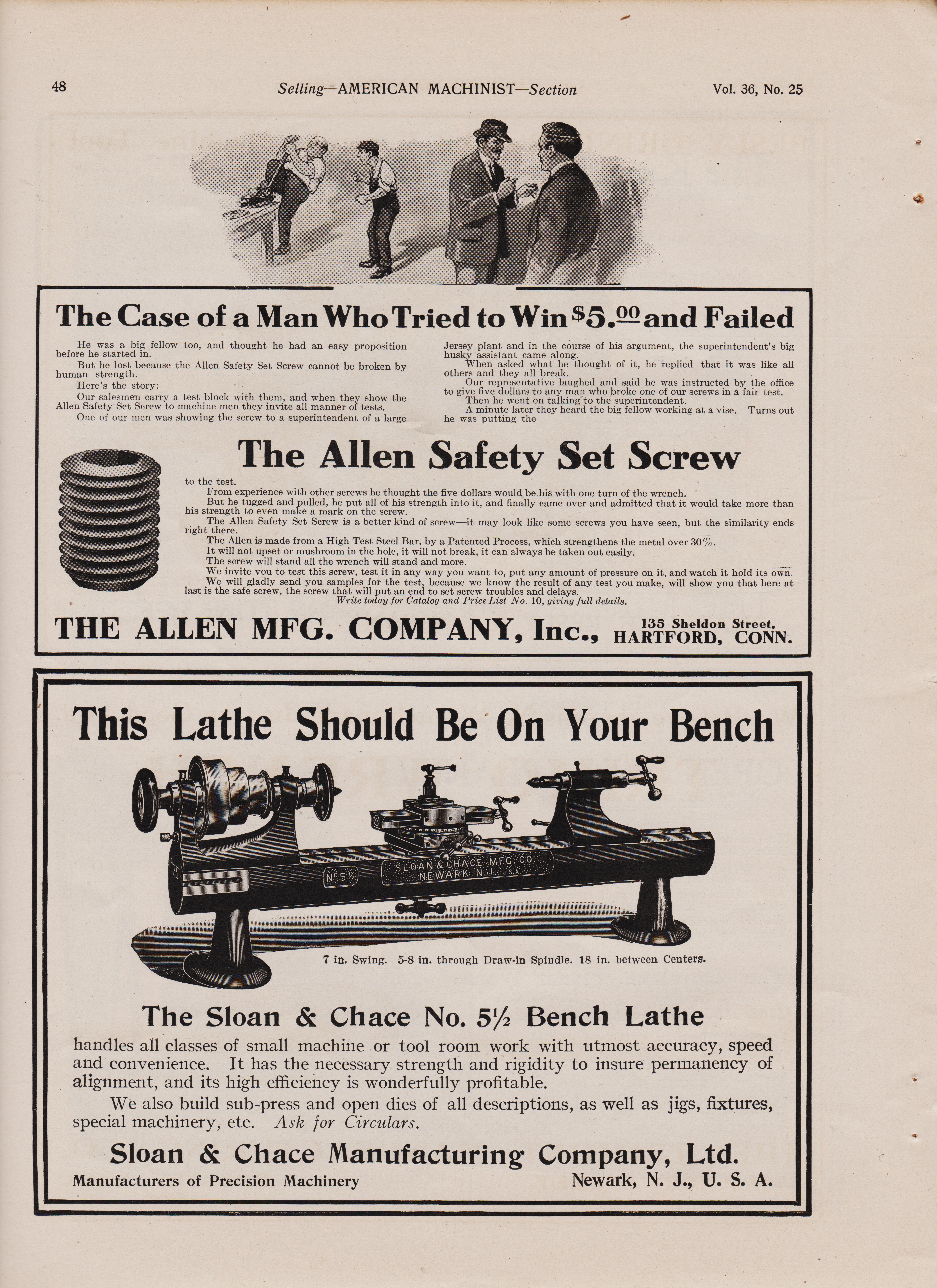
The Case of a Man Who Tried to Win $5.22 and Failed
He was a big fellow too, and thought he had an easy proposition before he started in. But he lost because the Allen Safety Set Screw cannot be broken by human strength. Here's the story: Our salesmen carry a test block with them, and when they show the Allen Safety Set Screw to machine men they invite all manner of tests. One of our men was showing the screw to a superintendent of a large
Jersey plant and in the course of his argument, the superintendent's big husky assistant came along. When asked what he thought of it, he replied that it was like all others and they all break. Our representative laughed and said he was instructed by the office to give five dollars to any man who broke one of our screws in a fair test. Then he went on talking to the superintendent. A minute later they heard the big fellow working at a vise. Turns out he was putting the
The Allen Safety Set Screw
to the test. From experience with other screws he thought the five dollars would be his with one turn of the wrench. But he tugged and pulled, he put all of his strength into it, and finally came over and admitted that it would take more than his strength to even make a mark on the screw. The Allen Safety Set Screw is a better kind of screw—it may look like some screws you have seen, but the similarity ends right there. The Allen is made from a High Test Steel Bar, by a Patented Process, which strengthens the metal over 30%. It will not upset or mushroom in the hole, it will not break, it can always be taken out easily. The screw will stand all the wrench will stand and more. We invite you to test this screw, test it in any way you want to, put any amount of pressure on it, and watch it hold its own. We will gladly send you samples for the test, because we know the result of any test you make, will show you that here at last is the safe screw, the screw that will put an end to set screw troubles and delays. Write today for Catalog and Price List No. 10, giving full details.
THE ALLEN MEG. COMPANY, Inc.,
*****************************************************************************************************************************************
This Lathe The Sloan & Chace No. 512 Bench Lathe.
handles all classes of small machine or tool room work with utmost accuracy, speed and convenience.
It has the necessary strength and rigidity to insure permanency of alignment, and its high efficiency is wonderfully profitable.
We also build sub-press and open dies of all descriptions, as well as jigs, fixtures, special machinery, etc.
Ask for Circulars. Sloan & Chace Manufacturing Company, Ltd. Manufacturers of Precision Machinery Newark, N. J., U. S. A. * .
Selling--AMERICAN MACHINIST--Section Vol. 36, No. 25
The Case of a Man Who Tried to Win $5.22 and Failed
He was a big fellow too, and thought he had an easy proposition before he started in. But he lost because the Allen Safety Set Screw cannot be broken by human strength. Here's the story: Our salesmen carry a test block with them, and when they show the Allen Safety Set Screw to machine men they invite all manner of tests. One of our men was showing the screw to a superintendent of a large
Jersey plant and in the course of his argument, the superintendent's big husky assistant came along. When asked what he thought of it, he replied that it was like all others and they all break. Our representative laughed and said he was instructed by the office to give five dollars to any man who broke one of our screws in a fair test. Then he went on talking to the superintendent. A minute later they heard the big fellow working at a vise. Turns out he was putting the
The Allen Safety Set Screw
to the test. From experience with other screws he thought the five dollars would be his with one turn of the wrench. But he tugged and pulled, he put all of his strength into it, and finally came over and admitted that it would take more than his strength to even make a mark on the screw. The Allen Safety Set Screw is a better kind of screw—it may look like some screws you have seen, but the similarity ends right there. The Allen is made from a High Test Steel Bar, by a Patented Process, which strengthens the metal over 30%. It will not upset or mushroom in the hole, it will not break, it can always be taken out easily. The screw will stand all the wrench will stand and more. We invite you to test this screw, test it in any way you want to, put any amount of pressure on it, and watch it hold its own. We will gladly send you samples for the test, because we know the result of any test you make, will show you that here at last is the safe screw, the screw that will put an end to set screw troubles and delays. Write today for Catalog and Price List No. 10, giving full details.
THE ALLEN MEG. COMPANY, Inc.,
*****************************************************************************************************************************************
This Lathe The Sloan & Chace No. 512 Bench Lathe.
handles all classes of small machine or tool room work with utmost accuracy, speed and convenience.
It has the necessary strength and rigidity to insure permanency of alignment, and its high efficiency is wonderfully profitable.
We also build sub-press and open dies of all descriptions, as well as jigs, fixtures, special machinery, etc.
Ask for Circulars. Sloan & Chace Manufacturing Company, Ltd. Manufacturers of Precision Machinery Newark, N. J., U. S. A. * .
June 20, 1912 Selling--AMERICAN MACHINIST--Section June 20, 1912
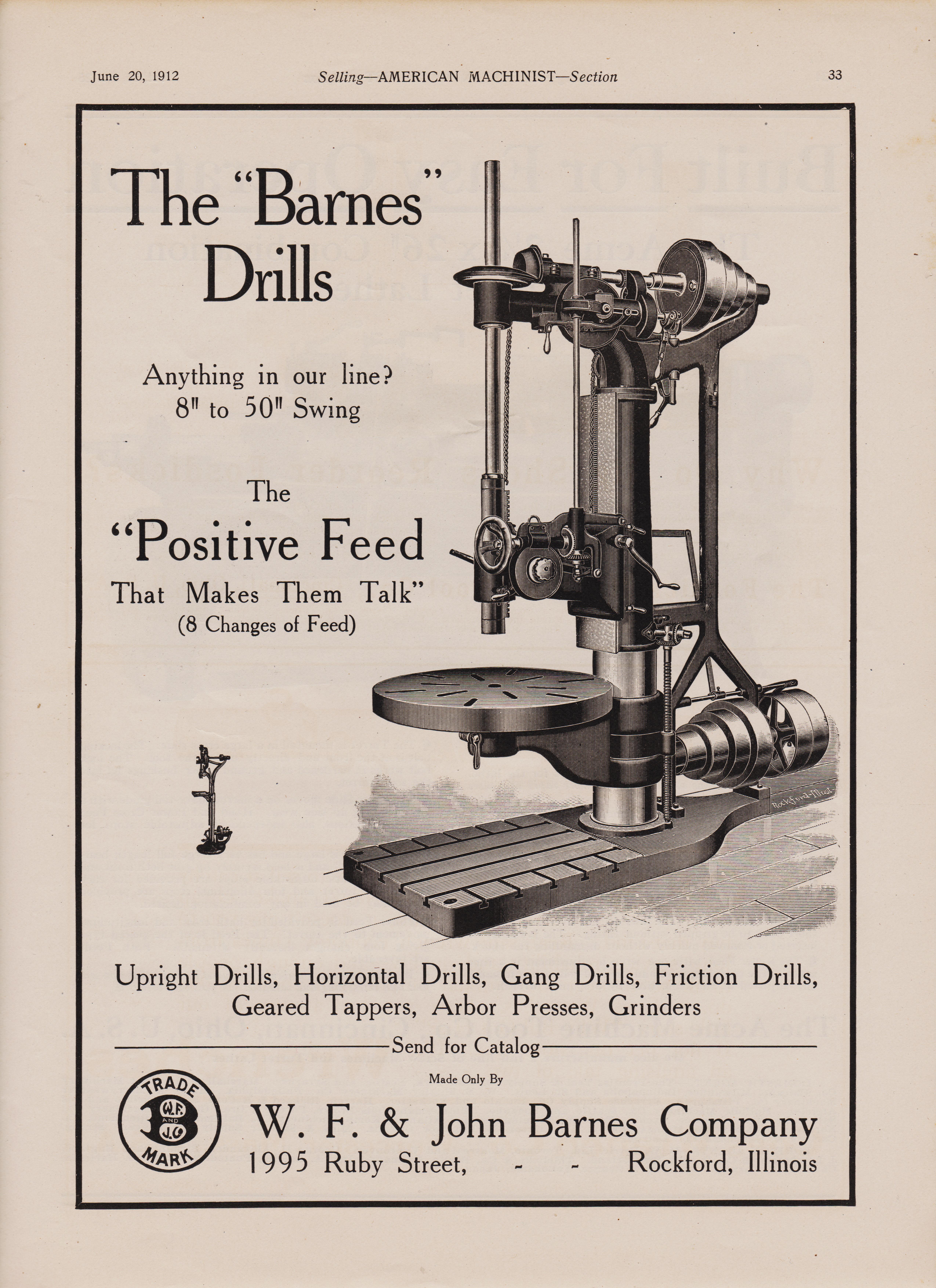
page 33
Upright Drills, Horizontal Drills, Gang Drills, Friction Drills, Geared Tappers, Arbor Presses, Grinders Send for Catalog
reed pic
page 33
Upright Drills, Horizontal Drills, Gang Drills, Friction Drills, Geared Tappers, Arbor Presses, Grinders Send for Catalog

page 48
Selling--AMERICAN MACHINIST--Section Vol. 36, No. 25
22 Selling—AMERICAN MACHINIST—Section Vol. 36, No. 25
26" Instantaneous Change Gear Engine Lathe Maximum Belt Pull Transmitted to the Cutting Tool The headstock is of the double back geared type. The double plate apron is of the most rigid construction possible. In every detail, this machine is strong, powerful and durable. It is the ideal tool for the modern machine shop. Rack cast in bed to engage pawl from tailstock.
The Boye Engine Lathes Write for Circular
Emmes Machine Tool Co. SUCCESSORS TO SCHUMACHER & BOYE Cincinnati, Ohio, U. S. A. WHEN RADIALS AND UPRIGHT DRILLS FALL SHORT for Power, Rigidity and Efficiency, our 40" and 60" HEAVY DRILLING, BORING, FACING and TAPPING MACHINES are "the" tools. They are designed for the heaviest drilling, boring, facing, tapping and trepan-ning bars and plates. In many instances they take the place of a boring mill at one-third outlay and are more convenient in handling. These machines we build in conjunction with our complete line of
RADIAL DRILLS DRESES MACHINE TOOL CO., Cincinnati, 0., U. S. A.
reed pic
Selling--AMERICAN MACHINIST--Section Vol. 36, No. 25
22 Selling—AMERICAN MACHINIST—Section Vol. 36, No. 25
26" Instantaneous Change Gear Engine Lathe Maximum Belt Pull Transmitted to the Cutting Tool The headstock is of the double back geared type. The double plate apron is of the most rigid construction possible. In every detail, this machine is strong, powerful and durable. It is the ideal tool for the modern machine shop. Rack cast in bed to engage pawl from tailstock.
The Boye Engine Lathes Write for Circular
Emmes Machine Tool Co. SUCCESSORS TO SCHUMACHER & BOYE Cincinnati, Ohio, U. S. A. WHEN RADIALS AND UPRIGHT DRILLS FALL SHORT for Power, Rigidity and Efficiency, our 40" and 60" HEAVY DRILLING, BORING, FACING and TAPPING MACHINES are "the" tools. They are designed for the heaviest drilling, boring, facing, tapping and trepan-ning bars and plates. In many instances they take the place of a boring mill at one-third outlay and are more convenient in handling. These machines we build in conjunction with our complete line of
RADIAL DRILLS DRESES MACHINE TOOL CO., Cincinnati, 0., U. S. A.
page 50
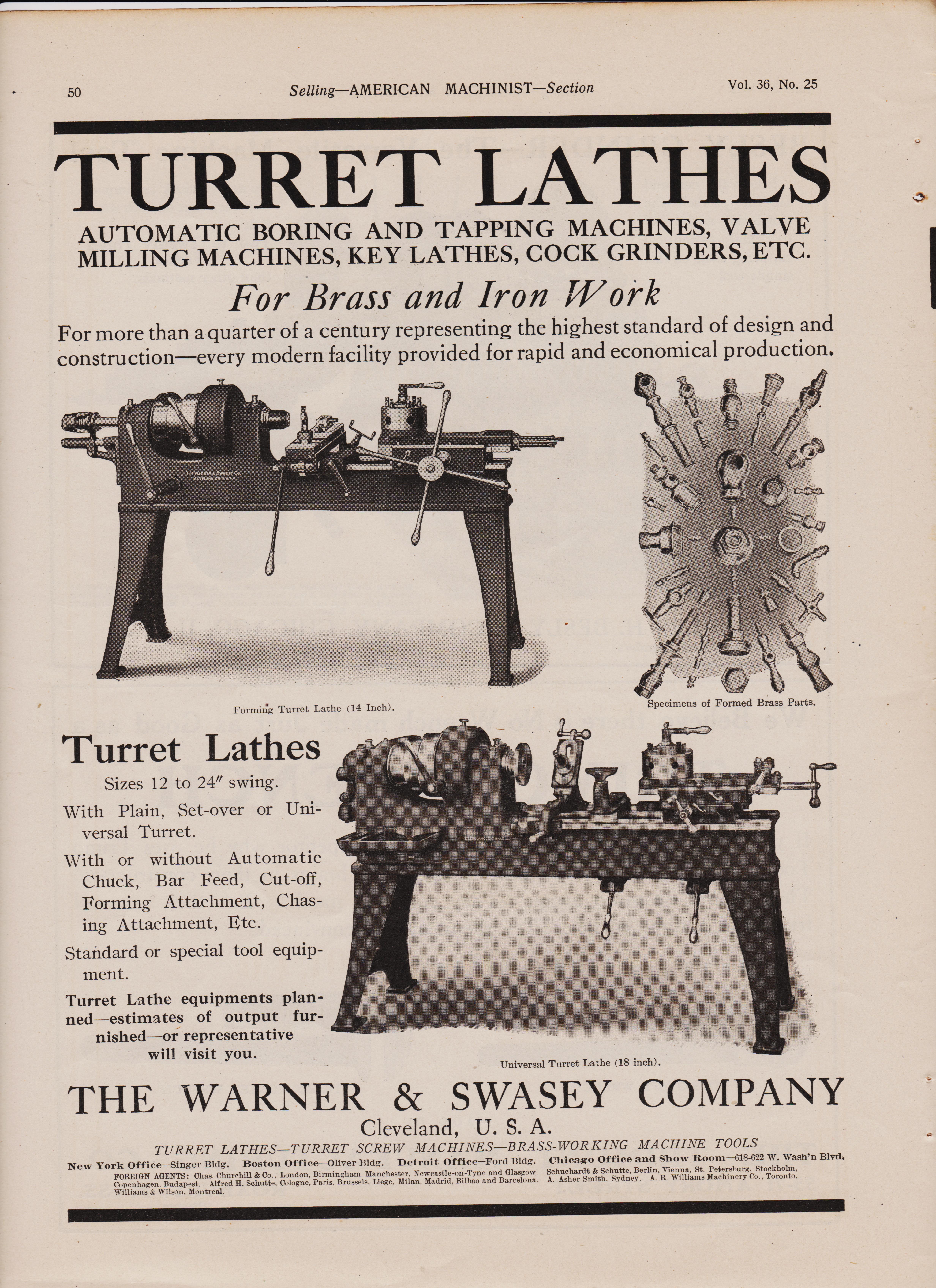
Selling--AMERICAN MACHINIST--Section Vol. 36, No. 25 TURRET LATHES
AUTOMATIC BORING AND TAPPING MACHINES, VALVE MILLING MACHINES, KEY LATHES, COCK GRINDERS, ETC. For Brass and Iron Work For more than a quarter of a century representing the highest standard of design and construction—every modern facility provided for rapid and economical production. Forming Turret Lathe (14 Inch).
Turret Lathes
Sizes 12 to 24" swing. With Plain, Set-over or Uni-versal Turret. With or without Automatic Chuck, Bar Feed, Cut-off, Forming Attachment, Chas-ing Attachment, Etc. Standard or special tool equip-ment. Turret Lathe equipments plan-ned estimates of output fur-nished or representative will visit you. Specimens of Formed Brass Parts.
Universal Turret Lathe (18 inch).
THE WARNER & SWASEY COMPANY Cleveland, U. S. A.
TURRET LATHES--URRET SCREW MACHINES—BRASS-WORKING MACHINE TOOLS New York Office--Singer Bldg. Boston Office—Oliver Bldg. Detroit Office—Ford Bldg. Chicago Office and Show Room-618-622 W. Wash'n Blvd. FOREIGN AGENTS: Chas. Churchill & Co., London, Birmingham. Manchester, Newcastle-on-Tyne and Glasgow. Schuchardt & Schutte, Berlin, Vienna, St. Petersburg, Stockholm, Copenhagen, Budapest. Alfred II. Schutte, Cologne, Paris. Brussels, Liege, Milan, Madrid, Bilbao and Barcelona. A. Asher Smith. Sydney. A. R. Williams Machinery Co., Toronto. Williams & Wilson, Montreal.
reed pic
Selling--AMERICAN MACHINIST--Section Vol. 36, No. 25 TURRET LATHES
AUTOMATIC BORING AND TAPPING MACHINES, VALVE MILLING MACHINES, KEY LATHES, COCK GRINDERS, ETC. For Brass and Iron Work For more than a quarter of a century representing the highest standard of design and construction—every modern facility provided for rapid and economical production. Forming Turret Lathe (14 Inch).
Turret Lathes
Sizes 12 to 24" swing. With Plain, Set-over or Uni-versal Turret. With or without Automatic Chuck, Bar Feed, Cut-off, Forming Attachment, Chas-ing Attachment, Etc. Standard or special tool equip-ment. Turret Lathe equipments plan-ned estimates of output fur-nished or representative will visit you. Specimens of Formed Brass Parts.
Universal Turret Lathe (18 inch).
THE WARNER & SWASEY COMPANY Cleveland, U. S. A.
TURRET LATHES--URRET SCREW MACHINES—BRASS-WORKING MACHINE TOOLS New York Office--Singer Bldg. Boston Office—Oliver Bldg. Detroit Office—Ford Bldg. Chicago Office and Show Room-618-622 W. Wash'n Blvd. FOREIGN AGENTS: Chas. Churchill & Co., London, Birmingham. Manchester, Newcastle-on-Tyne and Glasgow. Schuchardt & Schutte, Berlin, Vienna, St. Petersburg, Stockholm, Copenhagen, Budapest. Alfred II. Schutte, Cologne, Paris. Brussels, Liege, Milan, Madrid, Bilbao and Barcelona. A. Asher Smith. Sydney. A. R. Williams Machinery Co., Toronto. Williams & Wilson, Montreal.

page26
Selling--AMERICAN MACHINIST--Section Vol. 36, No. 25
This is the "PRECISION" BORING, DRILLING & MILLING MACHINE
Lucas Machine Tool Co.
AGENTS-C. W. Burton, Griffiths & Co., London. Alfred H. Schutte, Cologne, Berlin, Brussels, Paris, Barcelona, Bilbao. Donauwerk Ernst Krause & Co., Vienna, Budapest, Prague. Andrews A George, Yokohama, Japan, Overall, McCray, Ltd., Sydney, Australia. Williams & Wilson, Montreal, Canada. If you like its looks and are interested in its details, send for a circular. Then if you wish special information, send for our direct factory representative without obligation on your part. But the best thing is to call at our works.
***************************************************************************************************************
Cleveland, Ohio U. S. A.
S & S Gear Hobbing Machines
Made in 10 Different Sizes For over 40 years we have specialized in the manufacture of gear hobbing machines.
In ten different sizes, ranging from size No. 000 with an outside diameter of 4" to size No. 6 with an outside diameter of 158", we make a machine for every practical requirement.
S & S Gear Hobbing Machines
have reached a stage of development not equal-led by any other make. Over 1000 of them have been sold in Europe and America, and today they are the most universally used gear hobber on the market. We invite your comparisons and investigation. Let us send you the facts.
Our illustrated catalog describes and shows cuts of complete line. Write for a copy.
Schuchardt & Schutte Corner West and Cedar Streets, New York
https://antiquemachinery.com/images-2021/1912-American-Machinist-Magazine-1912-June-pg-18-Cleveland-Automatic-Lathe-Machine-o-Milled-Shaved-Threaded-Formed-cut-Off.jpeg
https://antiquemachinery.com/images-2021/1912-American-Machinist-Magazine-1912-June-pg-44--.jpeg
https://antiquemachinery.com/images-2021/1912-American-Machinist-Magazine-1912-June-pg-127-Blue-Chip-Bits-The-Tabor-Power-Squezing-Molding-Machine-Molding.jpeg
https://antiquemachinery.com/images-2021/1912-American-Machinist-Magazine-1917-March-3-pg-3-Pratt-and-Whitney-Co-Taps-small-tools.jpg
https://antiquemachinery.com/images-2021/1912-American-Machinist-Magazine-1912-June-pg-39-Die-Chaser-Grinder-Geometric-Tool-Co-Kerny-and-Trucker-Slotter-Attachment.jpeg
https://antiquemachinery.com/images-2021/1912-American-Machinist-Magazine-1912-June-pg-32-Co-wrench-The-Fosdick-macinneTool-Co-Boring-Mill.jpeg
https://antiquemachinery.com/images-2021/1912-American-Machinist-Magazine-1912-June-pg-29-Radial-Drill-Press-Joseph-T-Ryerson-and-Son-Prentice-Bros-Co-Machinery.jpeg
https://antiquemachinery.com/images-2021/1912-American-Machinist-Magazine-1912-June-pg-102-Modern-Cuter-grinder.jpeg
Selling--AMERICAN MACHINIST--Section Vol. 36, No. 25
This is the "PRECISION" BORING, DRILLING & MILLING MACHINE
Lucas Machine Tool Co.
AGENTS-C. W. Burton, Griffiths & Co., London. Alfred H. Schutte, Cologne, Berlin, Brussels, Paris, Barcelona, Bilbao. Donauwerk Ernst Krause & Co., Vienna, Budapest, Prague. Andrews A George, Yokohama, Japan, Overall, McCray, Ltd., Sydney, Australia. Williams & Wilson, Montreal, Canada. If you like its looks and are interested in its details, send for a circular. Then if you wish special information, send for our direct factory representative without obligation on your part. But the best thing is to call at our works.
***************************************************************************************************************
Cleveland, Ohio U. S. A.
S & S Gear Hobbing Machines
Made in 10 Different Sizes For over 40 years we have specialized in the manufacture of gear hobbing machines.
In ten different sizes, ranging from size No. 000 with an outside diameter of 4" to size No. 6 with an outside diameter of 158", we make a machine for every practical requirement.
S & S Gear Hobbing Machines
have reached a stage of development not equal-led by any other make. Over 1000 of them have been sold in Europe and America, and today they are the most universally used gear hobber on the market. We invite your comparisons and investigation. Let us send you the facts.
Our illustrated catalog describes and shows cuts of complete line. Write for a copy.
Schuchardt & Schutte Corner West and Cedar Streets, New York
pg 14
LETS GO AMERICAN MACHINIST-Section Vol. 56, No. 1
LET'S START RIGHT NOW!
.
LET'S START RIGHT NOW
To do those things necessary to bring conditions back to normal. We've faced business stag- nation long
enough now to know what it means; so let's go- let's get started on the right track again. This business de-
depression will last just as long as the people of this country sit back and wait for something to
happen-we've got to make things happen.
We can accomplish nothing by waiting for the other fellow to start something-the chances are he is sitting
back waiting for us. We've simply got to realize that it is up to everyone to do his share, and there never
was a better time than right now to start the ball a'rolling.
Then there is another and probably a much more threatening angle to the situation. The period of
prosperity just passed has witnessed a tremendous over-expansion in practically every industry, not only
in this country, but throughout the entire civilized world. `As a consequence, today, and likely for many
years to come, the facilities for production will be greater than the powers of absorption-which means the
keenest kind of competition and the weeding out of the less stable and less progressive concerns in
each industry. Business houses today are fighting for their very existence, and those who survive will be
the ones that start now to reduce their costs and better their methods, in order to meet the keenest
competition on a fair basis. ~
How should we begin? Where should we start?
If every manufacturer in the metal working industry would start by putting his own house in order, by
replacing his old worn'-out tools with new and better machines, by weeding out bis obsolete equipment,
and installing more modern, more profitable equipment in its place, the first thing you know, we would
have better business, things would begin to move again, and industry once more would "hit the trailof
progress. We, The American Tool Works Company, have already started. Since Jan. 1921, we have weeded
out of our own plant, eighty-three machines of different kinds, and are now replacing them with the latest
and most modern tools. By this we have provided business for the foundries, orders for the steel mills,
and work for a number of men-in other words, we have gone into action in our own plant.
If you will do the same in yours, the other fellow the same in his, and so on, ad infinitum, this country
would soon forget that there was a business depression, a readjustment period or a deflation spasm. It is
up to every one of us to put our shoulder to the wheel, so let's go-a slang expression -yes-but chuck full
of meaning and good advice.
The American Tool Works Co.
Cinncinatti, Ohio, U. S. A.
LATHES PLANERS--SHAPERS RADIALS
This is the 6 tst of a series of cost reducing advertisements. The president of every metal Fabricating
plant in this country should read each and every one of these advertisements, and then refer them to
his manager, CEO or superintendent.
top top sky pic top size
LETS GO AMERICAN MACHINIST-Section Vol. 56, No. 1
LET'S START RIGHT NOW!
.
LET'S START RIGHT NOW
To do those things necessary to bring conditions back to normal. We've faced business stag- nation long
enough now to know what it means; so let's go- let's get started on the right track again. This business de-
depression will last just as long as the people of this country sit back and wait for something to
happen-we've got to make things happen.
We can accomplish nothing by waiting for the other fellow to start something-the chances are he is sitting
back waiting for us. We've simply got to realize that it is up to everyone to do his share, and there never
was a better time than right now to start the ball a'rolling.
Then there is another and probably a much more threatening angle to the situation. The period of
prosperity just passed has witnessed a tremendous over-expansion in practically every industry, not only
in this country, but throughout the entire civilized world. `As a consequence, today, and likely for many
years to come, the facilities for production will be greater than the powers of absorption-which means the
keenest kind of competition and the weeding out of the less stable and less progressive concerns in
each industry. Business houses today are fighting for their very existence, and those who survive will be
the ones that start now to reduce their costs and better their methods, in order to meet the keenest
competition on a fair basis. ~
How should we begin? Where should we start?
If every manufacturer in the metal working industry would start by putting his own house in order, by
replacing his old worn'-out tools with new and better machines, by weeding out bis obsolete equipment,
and installing more modern, more profitable equipment in its place, the first thing you know, we would
have better business, things would begin to move again, and industry once more would "hit the trailof
progress. We, The American Tool Works Company, have already started. Since Jan. 1921, we have weeded
out of our own plant, eighty-three machines of different kinds, and are now replacing them with the latest
and most modern tools. By this we have provided business for the foundries, orders for the steel mills,
and work for a number of men-in other words, we have gone into action in our own plant.
If you will do the same in yours, the other fellow the same in his, and so on, ad infinitum, this country
would soon forget that there was a business depression, a readjustment period or a deflation spasm. It is
up to every one of us to put our shoulder to the wheel, so let's go-a slang expression -yes-but chuck full
of meaning and good advice.
The American Tool Works Co.
Cinncinatti, Ohio, U. S. A.
LATHES PLANERS--SHAPERS RADIALS
This is the 6 tst of a series of cost reducing advertisements. The president of every metal Fabricating
plant in this country should read each and every one of these advertisements, and then refer them to
his manager, CEO or superintendent.