Automatic-Gear-Cutting-Machines-Brown-and-Sharpe-Mfg-Co-1914
Automatic Gear Cutting Machines Brown and Sharpe Mfg Co 1914 Brown & Sharpe Machine shop Machines book operation
top
top
sky
pic top
size
title pic
top
top
sky
pic top
size
pic 1 first pale background top pic #cacaca #DCDFE1
It is 1914, What is going on....?
First World War erupts. ...On June 28, 1914, in an event that is widely regarded as sparking the outbreak of World War I, Archduke Franz Ferdinand, heir to the Austro-Hungarian empire, was shot to death by Bosnian Serb Gavrilo Princip in Sarajevo, Bosnia
.....Yes, Violence can effect change.......Just not the change you desire.
Just in time for income tax and the first industrial war to soon come,
Ford Motor Co wages jump from $2.40/9-hr day to $5.00/8-hr day.
Yuan Shih-k'ai, president of the new Chinese republic, dissolves parliament and prepares a constitution of his own design:
he will set himself up as dictator, preparatory to an attempt to make himself emperor.
(He will make it a powerful nation using chrony Capitalism,and then be able to do whatever he desires.)
Aspiring Dictators, here's how it's been done before, you can say that again.
,,,,and if you do not vote for them, they will give you a different kind of day too.
main text at top Machinist machinery March 1896
Pic cover top
https://antiquemachinery.com/images-2020/Automatic-Gear-Cutting-Machines-Brown-and-Sharpe-Mfg-Co-1914-Cover.jpg
alt="https://antiquemachinery.com/images-2020/Automatic-Gear-Cutting-Machines-Brown-and-Sharpe-Mfg-Co-1914-Cover.jpg"
first blue bar
top first pic blue barlink purple blue text
@@@@@2222222222@@@@@
first biildings Pic
alt="https://antiquemachinery.com/images-2020/Automatic-Gear-Cutting-Machines-Brown-and-Sharpe-Mfg-Co-1914-Inside-Cover-Factory.jpg"
top first pic blue barlink purple blue text
text pg 2
Automatic Gear Cutting Machines
for Spur and Bevel Gears Patented
January 26, 1904; September 1, 1908
Brown And Sharpe Automatic Gear Cutting Machines
for Spur and Bevel Gears -- Published 1914
Automatic Gear Cutting Machines for Spur and Bevel Gears printed 1914.
January 26, 1904; September 1, 1908
THE business now conducted by the Brown & Sharpe Mfg. Co. was founded in 1833 by David Brown and his son Joseph R. Brown. David Brown retired in 1841 and the business was continued by Joseph R. Brown until 1853, when Lucian Sharpe became his partner, and the firm of J. R. Brown & Sharpe was formed. The Brown & Sharpe Mfg. Co. was incorporated in 1868. The partnership of Darling, Brown & Sharpe was formed in 1866, and the business carried on under that name until the partnership was dissolved by the purchase of Mr. Darling's interest.
The Buildings are modern and especially arranged to meet the requirements of the business. The machine shops are fire-proof. The business, therefore, is free from danger of serious interruption and, on work entrusted to us, customers are given security against loss by fire. Floor Area. The eight main manufacturing buildings have a floor space of about 740,000 sq. ft., and the foundry about 245,000 sq. ft., the forging, hardening, central power plant and miscellaneous buildings about 215,000 sq. ft. In 1853 the floor space occupied was 1,800 sq. ft.; the present buildings have 1,200,000 sq. ft. of floor space, or over 27 acres.
******************first gear cutter*******************
second blue bar from top
2nd Pic building top
alt="http://antiquemachinery.com/images-2020/Machinery-Magazine-March-1896-vol-2-no-7-top-Cover-men-working-old-shop-lineshaft-belt-drive-1896%20(2).jpg"
55555555555555
Automatic-Gear-Cutting-Machines-Brown-and-Sharpe-Mfg-Co-1914-pg-6-no-13-Automatic-Gear-Cutting-Machine-gear-cutter.jpg
555555555555555555
2n Pic desc bot
alt="http://antiquemachinery.com/images-2020/Machinery-Magazine-March-1896-vol-2-no-7-page-211-bot-billings-and-spencer-co-drop-forging-hammer-shop.jpg"
whitney top first pic text
Page 5 Brown and Sharpe Automatic Gear Cutting Machines for Spur and Bevel Gears .
Page 5 .
January 26, 1904; September 1, 1908
The following are some of the important features that have been applied to these machines. The driving belt and ratio of gearing are amply proportioned to the capacity of the machines. The cutter speeds and feeds are independent of each other and the full range of feeds is available for each cutter speed. They are arranged in geometrical progression and can be easily changed. The bearing surfaces for the slides are large and the guiding ways are long in proportion to their width. The cutter and work spindles are exceptionally large in diameter.
All high speed bearings are bushed with bronze and the slides are oil ground so that oil finds its way to all parts of the sliding surfaces.
Adequate provision is made for protecting the working parts from dust and injury. The mechanisms for controlling the feed and speed of cutter, the return of cutter slide, and all change gears are enclosed in a suitable case at the ends of the machine and are easy of access.
The cutter slide carriage of the bevel gear cutting machine can be set and securely clamped at any angle from zero to
[pg. 5]
^^^^^^^^^^^^^^^^
gear cutter pg 7
https://antiquemachinery.com/images-2020/Automatic-Gear-Cutting-Machines-Brown-and-Sharpe-Mfg-Co-1914-pg-8-No-3-Heavy-Gear-Cutting-Machine.jpg
alt="http://antiquemachinery.com/images-2020/Machinery-Magazine-March-1896-vol-2-no-7-top-Cover-men-working-old-shop-lineshaft-belt-drive-1896%20(2).jpg"
gear cutter page 8
alt="https://antiquemachinery.com/images-2020/Automatic-Gear-Cutting-Machines-Brown-and-Sharpe-Mfg-Co-1914-pg-7.jpg"
^^^^^^^^^^^^^^^^^
Fifth pic down text
Page 7 Brown and Sharpe Automatic Gear cutter No 3 Heavy.
BROWN & SHARPE MFG. CO.
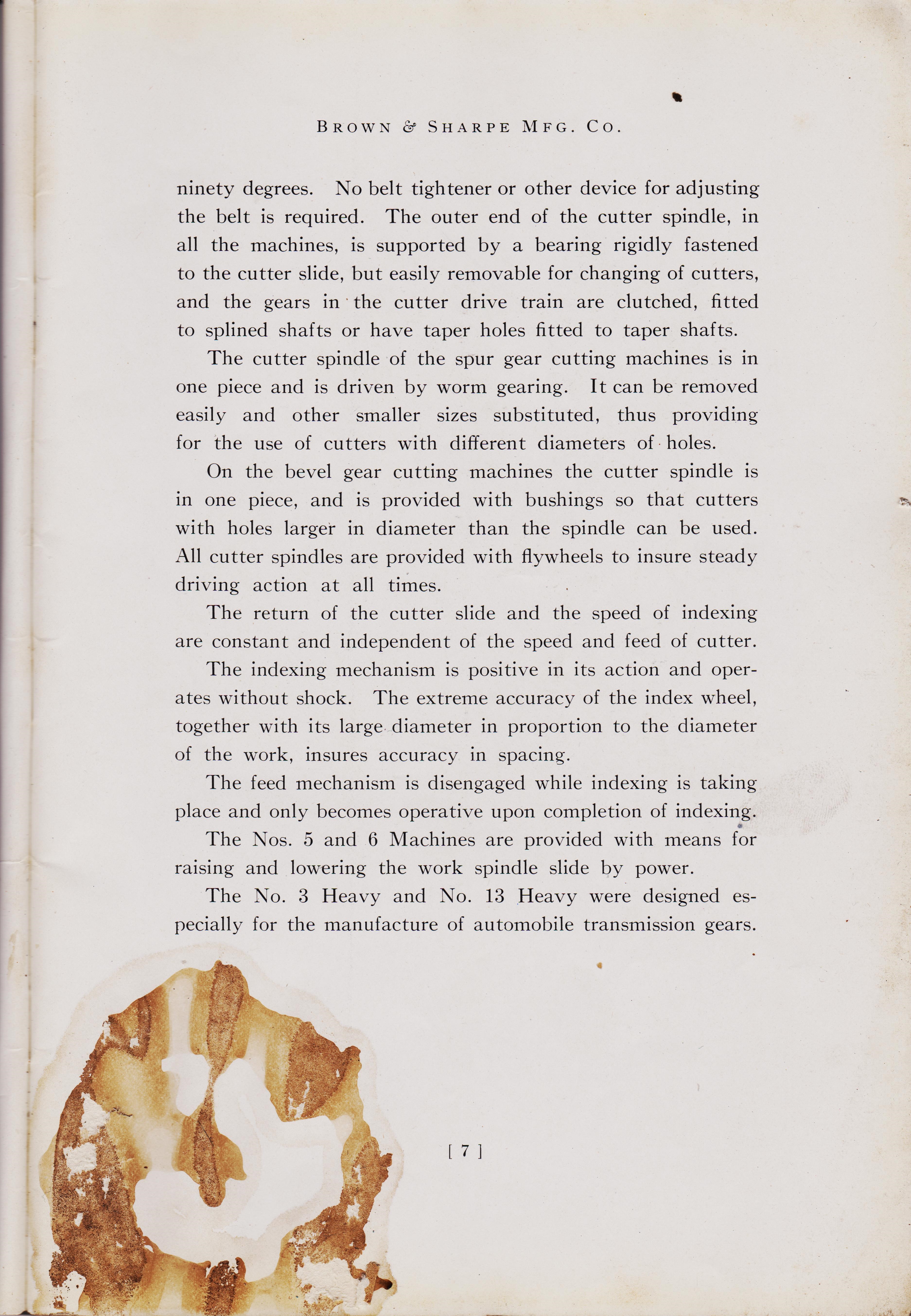
ninety degrees. No belt tightener or other device for adjusting the belt is required. The outer end of the cutter spindle, in all the machines, is supported by a bearing rigidly fastened to the cutter slide, but easily removable for changing of cutters, and the gears in the cutter drive train are clutched, fitted to splined shafts or have taper holes fitted to taper shafts. The cutter spindle of the spur gear cutting machines is in one piece and is driven by worm gearing. It can be removed easily and other smaller sizes substituted, thus providing for the use of cutters with different diameters of holes. On the bevel gear cutting machines the cutter spindle is in one piece, and is provided with bushings so that cutters with holes larger in diameter than the spindle can be used. All cutter spindles are provided with flywheels to insure steady driving action at all times.
The return of the cutter slide and the speed of indexing are constant and independent of the speed and feed of cutter.
The indexing mechanism is positive in its action and operates without shock. The extreme accuracy of the index wheel, together with its large diameter in proportion to the diameter of the work, insures accuracy in spacing.
The feed mechanism is disengaged while indexing is taking place and only becomes operative upon completion of indexing. The Nos. 5 and 6 Machines are provided with means for raising and lowering the work spindle slide by power.
The No. 3 Heavy and No. 13 Heavy were designed especially for the manufacture of automobile transmission gears.
[ 7 ]
**************************
6 pic down picture#6 pg 9
7 pic g10 gear cutter no 13h
6 pic down text
Page 9
Care of the Machines
Did anyone think to save these old Things. Did they hate everything that built them into who they were?
Page 9
BROWN & SHARPE MFG. CO.
Care of the Machines
As the life and efficiency of machines depend largely upon the amount of care taken of them, it is important that they should be kept clean and well oiled and that all repairs should be promptly attended to. In the following pages we offer some suggestions which, if carefully followed, will avoid annoyance and expense.
Oiling.
All worm gears and worms should be kept flooded with oil. We recommend an oil that is equal in all respects to the sample sent with the machine. As soon as the oil shows signs of becoming thick, it should be removed and new oil substituted. Suitable reservoirs for holding the oil are provided, having openings at 11 and 12,
Fig. 3.
The feed driving worm wheel at the left of the feed case may be oiled after lifting the cover 56, Fig. 3. The guiding ways of the cutter slide and the index worm and wheel should be kept clean and thoroughly oiled with a good machinery oil. Do not use the heavy oil except on the driving worm gears and worms. The cutter slide ways are oiled at 55,
Fig. 3 ;
the cutter slide feed screw and nut through the oil hole provided at 13, Fig. 3. Elevating Work Slide. In moving the work spindle slide when it is operated by power, be sure that all the clamps are loosened, and the hand elevating crank removed when one is used on shaft 21,
Fig. 3.
Adjustments. Careful attention is given to the adjustments of each machine before shipping and we caution against changing any of them except in case of wear or dismantling the machine. Instructions for adjusting end play of the cutter spindle, end play of cutter spindle worm, end play of feed screw, end play of index worm, and backlash between index worm and wheel are given on the instruction card sent with each machine.
[ 9 ]
###########
good
9 th pic back sec article top p200
http://antiquemachinery.com/images-2020/Machinery-Magazine-March-1896-vol-2-no-7-page-198-top.jpg

9 th pic bot p200
9'th pic down text
11xth pic down
Automatic-Gear-Cutting-Machines-Brown-and-Sharpe-Mfg-Co-1914-pg-11-
Indicator for setting up the cutter that came-with-origional-gear-cutting machine.
page 12 top
/
10'th pic down
Automatic-Gear-Cutting-Machines-Brown-and-Sharpe-Mfg-Co-1914-pg-13-
Indicator for setting up the cutter that came-with-origional-gear-cutting machine.
page 12 top
BROWN & SHARPE MFG. CO. page 11
Method of Setting Up and Operating a Spur Gear Cutting Machine
Adjusting Index Change Gears. First the proper change gears for the required number of divisions should be put in place on the indexing mechanism. The combinations necessary for different divisions are specified in the table sent with the machine, also on pages 50, 51, 52, 53 and 54, while the position of the change gears on the machine is indicated at 51, Fig. 1.
Fasten the gears in position, then lift the spring knob 38, Fig. 1,
and set the sliding block at the numbered recess corresponding with the number of turns of the locking disk required as given in the index table. When the gearing has been adjusted, it is a good plan to prove it to be correct by marking the index wheel, starting the machine and indexing it around, counting the number of teeth that will be cut.
Setting Cutter.
The cutter should now be selected and firmly secured on the arbor. In this position, it should be tested for true running, both at the side and periphery. If it runs out at the side, the grooves cut will not be the exact contour of the cutter teeth, and if it is eccentric, all of the cutting strain will be brought upon a few teeth. Unless these inaccuracies are minute or can be remedied another cutter should be used. When the cutter has been found to run satisfactorily it should be set exactly central with the work spindle. An indicator is furnished with all machines for this purpose. The sides of the teeth produced by a cutter that is not exactly central vary with relation to radial lines; hence the bearing on the teeth of the gears when in mesh is not correct and the result is noisy running gears. If the cutter is not central it will be noticed that the gears run more quietly in one direction than the other. *********
page 13****BROWN & SHARPE MFG. CO.
To set the cutter central, loosen nut 15, Fig. 3, and, after removing the dust guard, clamp the indicator, Fig. 2,
to the ways of the bed in front of the cutter slide, in a position to allow the screw J to be adjusted so the point will touch the cutter about on the pitch line. Indicate the opposite sides of the cutter by reversing the arm K on the pin L.
Fig. 2 Indicator for Setting Cutter
Adjust the cutter spindle by means of the worm 14, Fig. 3,
until the zero on arm K is equidistant from zero on the plate when the arm K is in either position, then clamp with nut 15, Fig. 3.
If preferred, the screw J can be adjusted so that when cutter is central, the two zero lines will be together in both positions of the arm.
[ 13
***************************
&&&&&&&&&&&&&&&&&&
12 page 1 top
https://antiquemachinery.com/images-2020/Automatic-Gear-Cutting-Machines-Brown-and-Sharpe-Mfg-Co-1914-pg-1-.jpg
Sixth pic down
Care and Use of Automatic Gear Cutting Machines For Spur and Bevel Gears.
HELICAL GEARING.
/
Care and Use of Automatic Gear Cutting Machines For Spur and Bevel Gears.
TRADE MARK
Brown & Sharpe Mfg. Co. Providence, R. I., U. S. A.
Fig. 1 Rear Elevation
No. 5 Automatic Spur Gear Cutting Machine
page 19
88888888888888
page 9
&&&&&&&&&&&&&&&&&&&&&&&&&&
130 add
&&&&&&&&&&&&&&&&&&&&&&&&&&&&&
12 page top pg 203 helical 18700
&&&&&&&&&&&&&&&&&&&&&&&&&&&&&&&&&&&&&&&&&&&&&&&&&&&&&&&&&&&&&&&&&&&&&&&&&&&
title text
width="843" height="784" alt="">
11 pic down text
Fig. 3 Plan No. 5 Automatic Spur Gear Cutting Machine
Automatic-Gear-Cutting-Machines-Brown-and-Sharpe-Mfg-Co-1914-pg-9-Care-of-the-Gear-Cutting-Machines
/
Fig. 3 Plan No. 5 Automatic Spur Gear Cutting Machine
*********************************************************************
Automatic-Gear-Cutting-Machines-Brown-and-Sharpe-Mfg-Co-1914-pg-15-How-to-set-up-Gear-Cutting-Machine.jpg
title text
width="843" height="784" alt="">
11 pic down text
/
BROWN & SHARPE MFG. CO.
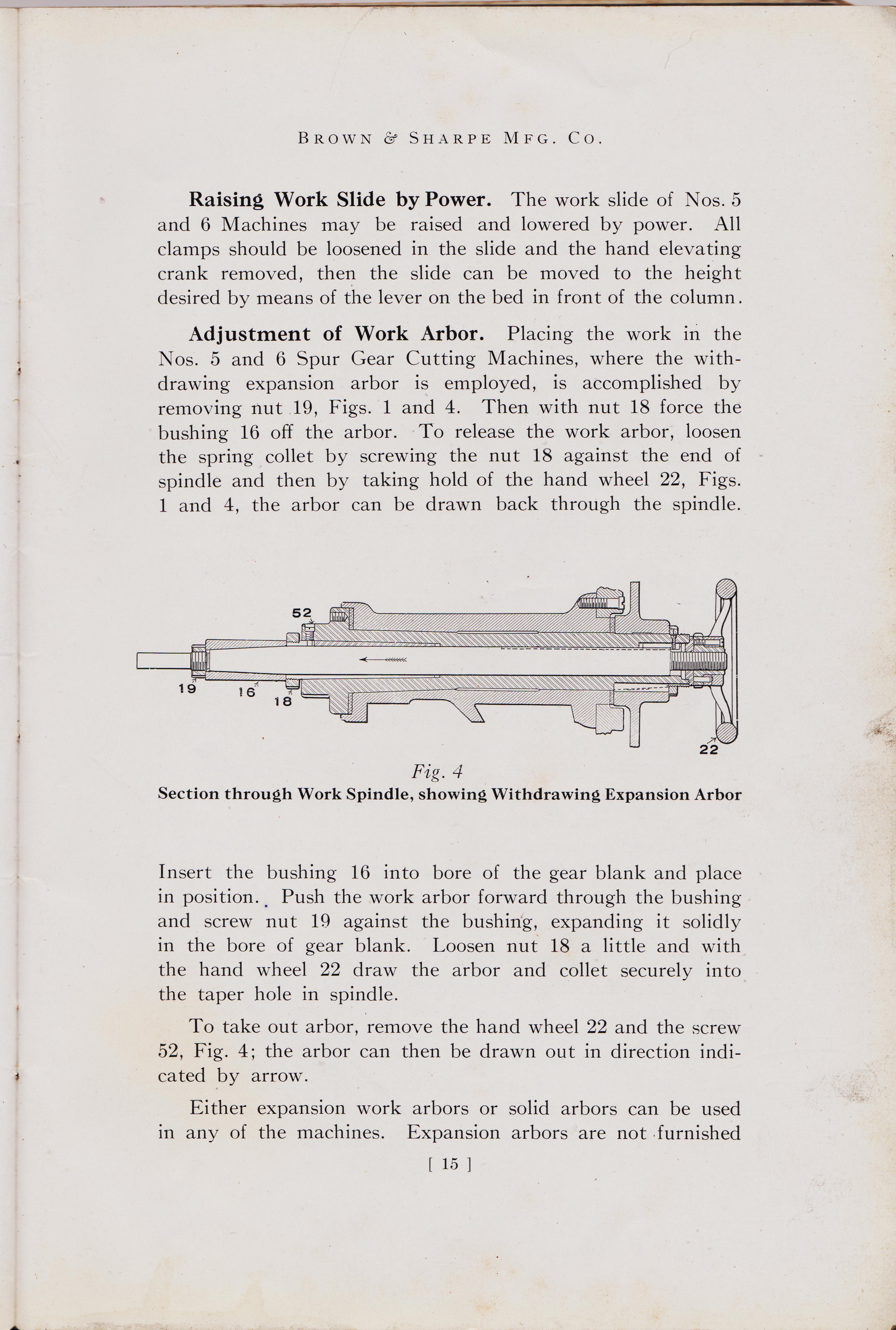
Raising Work Slide by Power. The work slide of Nos. 5 and 6 Machines may be raised and lowered by power. All clamps should be loosened in the slide and the hand elevating crank removed, then the slide can be moved to the height desired by means of the lever on the bed in front of the column. Adjustment of Work Arbor. Placing the work in the Nos. 5 and 6 Spur Gear Cutting Machines, where the with-drawing expansion arbor is employed, is accomplished by removing nut 19, Figs. 1 and 4. Then with nut 18 force the bushing 16 off the arbor. To release the work arbor, loosen the spring collet by screwing the nut 18 against the end of spindle and then by taking hold of the hand wheel 22, Figs. 1 and 4, the arbor can be drawn back through the spindle.
Fig. 4 Section through Work Spindle, showing Withdrawing Expansion Arbor
Insert the bushing 16 into bore of the gear blank and place in position.. Push the work arbor forward through the bushing and screw nut 19 against the bushing, expanding it solidly in the bore of gear blank. Loosen nut 18 a little and with the hand wheel 22 draw the arbor and collet securely into the taper hole in spindle. To take out arbor, remove the hand wheel 22 and the screw 52, Fig. 4; the arbor can then be drawn out in direction indi-cated by arrow. Either expansion work arbors or solid arbors can be used in any of the machines. Expansion arbors are not furnished
pg[ 15 ]
title text
((((((((((((((((((((((((((((((((((((((((((((((((((((((((((((((
Automatic-Gear-Cutting-Machines-Brown-and-Sharpe-Mfg-Co-1914-pg-15-How-to-set-up-Gear-Cutting-Machine.jpg
width="843" height="784" alt="">
11 pic down text
Page 16 Automatic-Gear-Cutting-Machines-Brown-and-Sharpe-Mfg-Co-1914-page-16-How-to-set-up-Gear-Cutting-Machine
/
BROWN & SHARPE MFG. CO.
with the Nos. 3 and 4 Machines, but can be supplied when desired. Where the expansion arbor is not used, .a solid arbor must be selected that closely fits the hole in the blank. Care should be taken that it runs true on centres and is also true when firmly secured in the hole in the work spindle. To get accurate gears an arbor should not run out over one-half of one-thousandth of an inch.
Setting the Blank.
Before placing the blank upon the arbor the outside diameter should be measured and compared with the correct outside diameter for the pitch and number of teeth to be cut. If it is a little under size, compensation should be made in setting the gear tooth caliper for depth to pitch lineone-half the amount the blank is under size should be taken from the depth to the pitch line. If the blank is over size it should be returned to the lathe and reduced to the proper diameter. Test the blank for true running while it is loose upon the arbor. If it runs out very much either discard it or have the inaccuracy remedied; but if it is slight, mark the high spot and be sure it comes in the same place when the blank is tightened up; the pitch circle will then be concentric with the center hole. To test the gear when it has been tightened up, disconnect the index worm by loosening the clamping lever 31, Fig. 1, and turning the knob 30; then turn the wheel by hand. Also test the side of the gear to see that it does not wabble, or bind against the rim rest if one is used. When this has been done, and the index worm returned to its working position in the wheel, trip the indexing mechanism once after starting the machine in order to take up any backlash in the gears.
Selecting Change Gears for Cutter Spindle Speed.
While exact cutter speeds cannot be given, owing to variation in the conditions surrounding the work, the following suggestions may be found helpful to the inexperienced operator. Under average conditions carbon steel cutters may be run from 60 to 70 feet per minute in cast iron, and from 30 to 40 feet per minute in machinery steel.
[ 16 ]
 width="843" height="784" alt="">
11 pic down text
+++++++++++++++++++++++++++++++++++++++++++++++
width="843" height="784" alt="">
11 pic down text
+++++++++++++++++++++++++++++++++++++++++++++++
href https://antiquemachinery.com/images-2020/Automatic-Gear-Cutting-Machines-Brown-and-Sharpe-Mfg-Co-1914-pg-1-.jpg
/
BROWN & SHARPE MFG. CO.
High-speed steel cutters can be run from 80 to 125 feet per minute in cast iron, and from 65 to 100 feet per minute in machinery steel. It should be borne in mind that the speed of the cutter may be anywhere within these limits, or even in extreme instances greater or less. It varies in every case according to the quality of material to be cut, accuracy of finish desired, rigidity of gear blank and kind of lubricant used. All these factors should be considered when deciding on the cutter speed. For tables of revolutions per minute for various cutting speeds and diameters, see pages 60 and 61. The change gears necessary to give the speed desired, as indicated on the speed table furnished with the machine, are placed in position as shown at 53,
Fig. 3. For tables of speeds and feeds, see pages 55, 56, 57, 58 and 59. Feed of Cutter Slide. The rate of feed varies so widely under different conditions, while slight changes have so marked an effect on the cost and quality of the product, that no exact rates can be given as the correct ones. The best method is to start with a moderate feed, then increase it until the gear blank will stand no more or the economical limit of the cutter is reached. The frequency with which the cutter must be ground to keep it in good condition shows whether it is being driven nearly to its limit. If it becomes dull very quickly, the feed is probably too fast and should be reduced, there being danger of burning the cutter. On the other hand, a cutter that runs long periods without becoming dull may safely be fed faster. The most economical feed is usually not the fastest which the cutter will stand without burning or breaking. This is due to the fact that with a very high rate of feed the cutter must be ground frequently, which consumes considerable time. There is also the risk of a ruined cutter. A slightly slower feed in such a case will not greatly decrease the rate of production, while it will, on the other hand, cause the cutter to hold its edge several times as long, as a rule. The result is that the net production per cutter will be greater at the slower feed and the production per day may be as great. This reduces the cutter cost per gear produced, since the cutters last much longer under the slightly slower feed. [ 17 ]
+++++++++++++++++
width="843" height="784" alt="">
11 pic down text
11 pic down text
Automatic-Gear-Cutting-Machines-Brown-and-Sharpe-Mfg-Co-1914-page-18-How-to-set-up-Gear-Cutting-Machine.jpg.
Brown & Sharpe Mfg. Co. Providence, R. I., U. S. A.
Feed Of High-Speed-Cutters
Setting Reversing-Dogs
Ajusting for Depth of Tooth
page 18
/
BROWN & SHARPE MFG. CO.
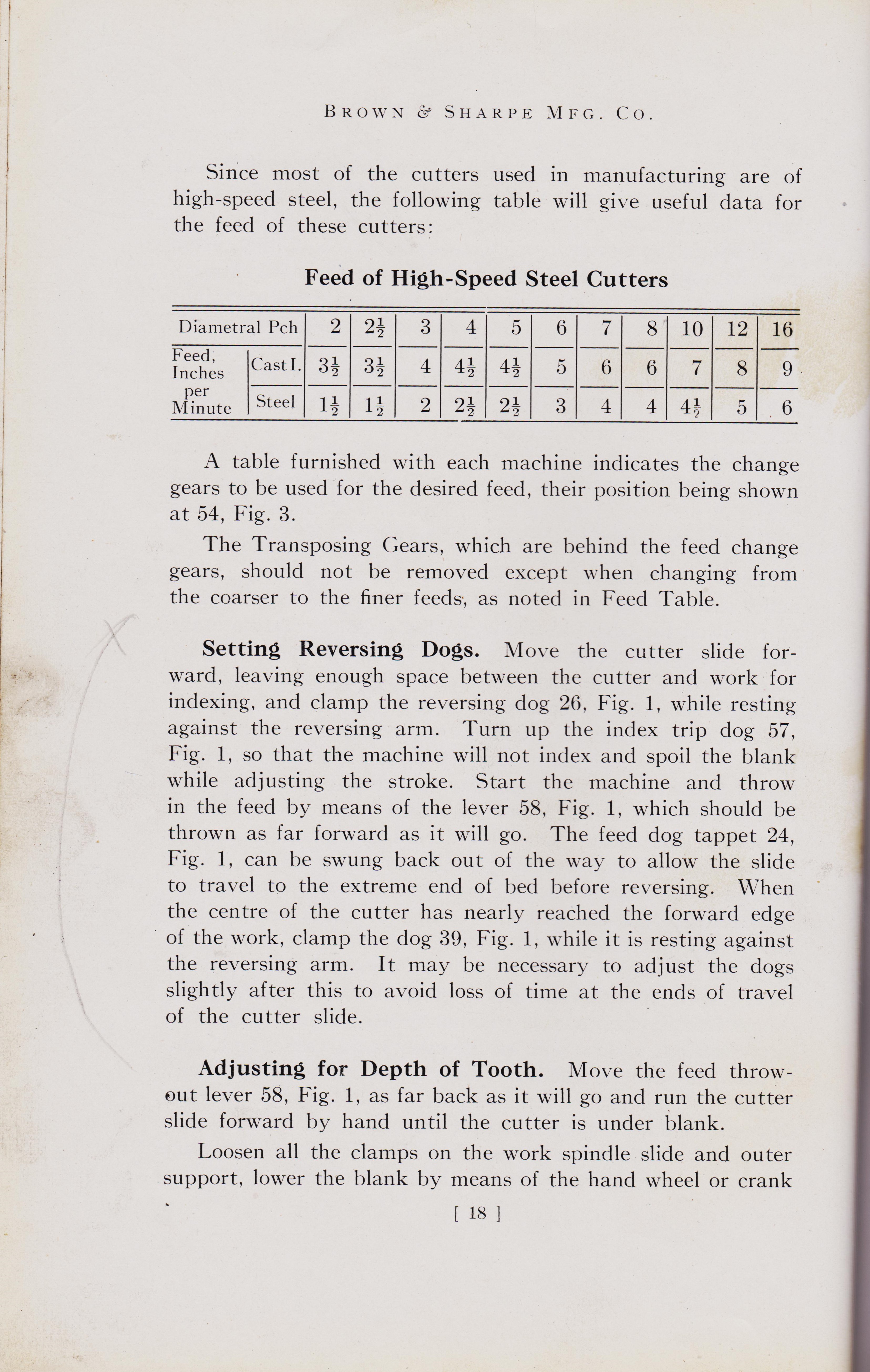
Since most of the cutters used in manufacturing are of high-speed steel, the following table will give useful data for the feed of these cutters:
Feed of High-Speed Steel Cutters
Diametral Pitch 2
Feed, Inches per Minute
Cast I. Steel
A table furnished with each machine indicates the change gears to be used for the desired feed, their position being shown at 54, Fig. 3. The Transposing Gears, which are behind the feed change gears, should not be removed except when changing from the coarser to the finer feeds, as noted in Feed Table.
Setting Reversing Dogs.
Move the cutter slide for-ward, leaving enough space between the cutter and work for indexing, and clamp the reversing dog 26, Fig. 1, while resting against the reversing arm. Turn up the index trip dog 57, Fig. 1, so that the machine will not index and spoil the blank while adjusting the stroke. Start the machine and throw in the feed by means of the lever 58, Fig. 1, which should be thrown as far forward as it will go. The feed dog tappet 24, Fig. 1, can be swung back out of the way to allow the slide to travel to the extreme end of bed before reversing. When the center of the cutter has nearly reached the forward edge of the work, clamp the dog 39, Fig. 1, while it is resting against the reversing arm. It may be necessary to adjust the dogs slightly after this to avoid loss of time at the ends of travel of the cutter slide.
Adjusting for Depth of Tooth. Move the feed throw-out lever 58, Fig. 1, as far back as it will go and run the cutter slide forward by hand until the cutter is under blank. Loosen all the clamps on the work spindle slide and outer support, lower the blank by means of the hand wheel or crank
[18]
+++++++++++++++++++
+++++++++++++++++

width="843" height="784" alt="">
11 pic down text
/
BROWN & SHARPE MFG. CO.
at 21, Fig. 3, until the cutter, which should be running, just touches the blank. Move the cutter slide back by throwing the reversing lever 27, Fig. 3, to the right until the cutter will clear the blank. To take out any backlash there may be in the elevating screw, turn the hand wheel or crank a little in the opposite direction. Set the dial 20, Fig. 3, at zero, then lower the work spindle slide a little more than the depth required and raise it until the dial 20, will read the proper depth for the pitch to be cut, making proper allowance in case the blank is turned too small. By this method the weight of the various parts will rest upon the screw and the slide will be less likely to change position when clamping. After the work is properly set, clamp the work spindle slide first and then the outer support. In tightening the work slide be sure to tighten the bolts on the left-hand side of the head and then tighten those on the right-hand side, as this brings the work spindle slide up into position in case a heavy blank has caused it to sag when the bolts were loosened.
Setting Rim Rest. Place the rim rest shown at 28, Fig. 1, in position, setting it high enough to clear the cutter. Care should be taken that the rim rest does not bind the blank at any point. To test the adjustment of the rim rest, disengage the worm and wheel and turn the work spindle by hand. After testing the adjustment engage the worm and wheel again and clamp securely by means of handle 31, Fig. 1.
Taking Trial Cuts.
The machine is now ready to take trial cuts. Allow the cutter to advance far enough into the blank to give the groove its full form for a short distance; then reverse it, index one space, and make a similar cut.
When the two trial grooves are cut, trip the indexing mechanism until they are brought into a position where it is possible to measure them. Measure the tooth for thickness at the pitch line. If it is not quite the required thickness, adjust the work slide a little and take trial cuts until the correct thickness is obtained, then go ahead and cut completely around.
[ 19 ]
+++++++++++++++++++
11 pic down text
Automatic-Gear-Cutting-Machines-Brown-and-Sharpe-Mfg-Co-1914-page-20-How-to-set-up-Gear-Cutting-Machine
page 19
+++++++++++++++++
width="843" height="784" alt="">
11 pic down text
+++++++++++++++++++
11 pic down text
Automatic-Gear-Cutting-Machines-Brown-and-Sharpe-Mfg-Co-1914-page-20 Micrometer measuring Gear-Cutting-Machine.jpg.
A
page 20
/
BROWN C SHARPE MFG. CO.
Gauging Teeth.
To measure or gauge the teeth of a gear while in a machine, lift the feed dog tappet 24, Fig. 1, to clear the reversing arm, and run the cutter slide back out of the way. A gear tooth caliper as shown in Fig. 9 is a very desirable tool for this purpose. The adjustments of the dogs 26 and 39, Fig. 1, need not be altered and the tappet 24 will automatically take its proper position when the cutter slide is run forward.
Re-Cutting Gears.
If it is desired to re-cut a gear or to cut out a bad place in the blank after it has been secured on the arbor, loosen the clamp screw 29, Fig. 1, and adjust the blank to the proper position by turning the knob 33, then clamp with the screw 29.
Depth of Gear Tooth Micrometer No. 249
0=9,1,6=6
For Scribing the Whole Depth of Space on Gear Blanks
[ 20 ]
$$$$$$$$$$$$$$$$$$$$$$$$$$$$$$$$$$$$$
width="843" height="784" alt="">
11 pic down text
+++++++++++++++++++
11 pic down text
Automatic-Gear-Cutting-Machines-Brown-and-Sharpe-Mfg-Co-1914-page-20 Micrometer measuring Gear-Cutting-Machine.jpg.
A
page 20
/
BROWN C SHARPE MFG. CO.
Gauging Teeth.
To measure or gauge the teeth of a gear while in a machine, lift the feed dog tappet 24, Fig. 1, to clear the reversing arm, and run the cutter slide back out of the way. A gear tooth caliper as shown in Fig. 9 is a very desirable tool for this purpose. The adjustments of the dogs 26 and 39, Fig. 1, need not be altered and the tappet 24 will automatically take its proper position when the cutter slide is run forward.
Re-Cutting Gears.
If it is desired to re-cut a gear or to cut out a bad place in the blank after it has been secured on the arbor, loosen the clamp screw 29, Fig. 1, and adjust the blank to the proper position by turning the knob 33, then clamp with the screw 29.
Depth of Gear Tooth Micrometer No. 249
Depth of Gear Tooth Micrometer.
For Scribing the Whole Depth of Space on Gear Blanks
[ 20 ]
$$$$$$$$$$$$$$$$$$$$$$$$$$$$$$
$$$$$$ brochere
width="1092" height="759"
alt=""
>
11 pic down text
$$$$$
width="1092" height="759"
alt="">
11 pic down text
$$$$
width="900" height="600"
alt="">
11 pic down text
^^^^^^^^^^^^^^^^^^^^^^^^^^^^^^^^^^^^^^^^^^^^^^^^^^^^
old pic last amer mach


