

/images-scientific-american


20834 retest SCIENTIFIC AMERICAN SUPPLEMENT, No. 1300.
pg 337 NOVEMBER 25, 1876.
>337 NER 25, 1876.1 337 aaddd Scientific-American-Nov-25-1876-p339-bot.jpeg

******************
Our molootIonn this week from Knight's " Mechanical Dic-tionary" (published
in numbers by Messrs. Hurd & Houghton, Now York city) include a number of interesting engravings of locomoti yes, among which will be found represented the early machines of Stephenson and others, now carefully preserved OH historical relics. We also give illustrations of two rail-ways of curious construction. The FERRY RAILWAY, , has its track on the bottom of a water course, and Fig. 1. Ferry- Railway. pg-339 the carriage which runs thereon has an elevated deck which supports the train. Chains are attached to the carriage and connected to engines on each side of the stream, and in this way the huge vehicle is pulled from shore to shore. A fer-ry of this kind is in existence at St. Malo, France, and there are others in various parts of Holland. It is a cheap sub-stitute for a railway bridge, Fig. 2 represents Vignolles and Ericsson's CENTRAL FRICTION RAIL,
Scientific-American-Nov-25-1876-p339-bot.jpeg
*****************************************************************************************************************************************************
Scientific-American-Nov-25-1876-p339-bot.jpeg
NOVEMBER, 25, 1876. page 341
NOV 25, 1876. pg 341
sorry I can gi ye so few data regarding an event of which I Ipattern work are made very fine, in fact merely distinguish-am am certain as of my own existence. The clear but pecul- able; and the instrument by which they are drawn is shown lar (44 of that region in summer may account for the dis-m.1,1149414 of the view. W ash ngton, D. C.
RICHARD COVINGTON.PRACTICAL MECHANISM, BY JOSHUA ROSE .SECOND SERIES-Number XV.
PATTERN MAKING. Our second example, Fig. 106, is a design for another kind of gland, such as is often fitted to glands for pump rods and spindles. For the small sizes, the glands are usually cast solid, and the hole is drilled out in the lathe, in which case, providing the gland is not very deep, it would be molded vertically, with the head in the nowel, and would be turned out of the solid piece of wood in the style of our previous example, treating for the moment the hexagonal part as a flange, whose diameter must be turned to the size of the hexagon across the corners. After the turning is done, we mark the hexagon as follows. We set a pair of compasses as nearly as possible to the radius of the turned piece that is to form the hexagon, and divide that piece off into six divisions, in the manner shown in Fig. 107 ; for the radius of a circle will divide its circumference into six equal parts. So that, i f the compasses are correctly set, one trial will be sufficient ; but if not, we must readjust the compasses and go around again. Then, from these points, we square lines, as shown in Fig. 107, at 1, 2, 3, 4, 5, 6 ; and then, with the paring chisel, we pare off tho sides to the lines. It is not necessary to actually draw the hexagon on the circumference by join-ing the lin(Is of di vit41011 ol► tho top of the flange; for a in Fig. 110. It is called a cutting scriber, and the end at A is beveled off at both sides, like a skew chisel, forming a knife edge. The end, B, is ground to a point, and both ends are finished on an oilstone. The point end is for drawing lines along the grain, while the cutting edge, A, is for draw-ing lines across the grain of the wood. The wooden handle in the center is to enable the operator to hold it more firm-ly. It sometimes happens that the size of the hexagon is given across the flat sides instead of over the angle; and when that is so, we proceed as follows : We describe upon a piece of board, as in Fig. 111, a circle of a diameter equal to the given distance between the flat sides. We then take a hexagon gage, or else set the bevel square to an angle of 120°: and applying it to the planed edge of the board, we draw the line, C D, in Fig. 111, in which figure, A is the circle of the size of the flat sides of the hexagon, and B E are the planed edges of the board. We next reverse the be-vel; and from the opposite edge of the board we strike the line, F D, cutting C D at the point, D, where both the lines cut the circumference of the circle, A. Then from the cen-ter of the circle, A, we draw the circle, G, intersecting the point, D. The diameter of G will be the size of the hexa-gon across the corners. If the gland is a long one, it will be better to make it in 1 F to test its strength in comparison with hempen rope and chain, as regarded weight, size, strength, price, durability, and economy. This required time, patience, and a heavy outlay of capital. On January 12, 1835, the first patent was obtained by Mr. Smith, and in 1839 he had obtained his fourth patent.
Stick to a Legitimate Business. Well directed energy and enterprise are the life of Ameri-can progress ; but if there is one lesson taught more plainly than others by the great failures of late, it is that safety lies in sticking to a legitimate business. No man—manufacturer, trader, or banker—has any moral right to be so energetic and enterprising as to take from his legitimate business the cap-ital which it requires to meet any emergency. Apologies are sometimes made, for firms who have failed, by recurring to the important experiments they have aided, and the unnumbered fields of enterprise where they have freely scattered their money. We are told that individual losses sustained by those failures will be as nothing com-pared with the benefits conferred on the community by their liberality in contributing to every public work. There is little force in such reasoning. A man's relations to a credi-tor are vastly different from his relations to what is called the public. The demands of the one are definite, the claims of the other are just what the ambition of the man may make them. The histories of honorably successful business men unite to exalt the importance of sticking to a legitimate business ; and it is most instructive to see that, in the greater portion of the failures, the real cause of disaster was the branching out beyond a legitimate business, in the taking hold of this and that tempting offer, and, for the sake of some great gain, venturing where they did not know the ground, and could not know the pitfall.
The inventor of Gas Lights. The inventor of gas lights is said to have been a French-man, Philippe Le Bon, an engineer of roads and bridges, who in 1782 adopted the idea of using, for the purpose of illumination, the gases distilled during the combustion of wood. He labored for a long time in the attempt to perfect his crude invention, and it was not until 1799 that he con-fided his discovery to the Institute. In September, 1800, he took out a patent, and in 1801 he published a memoir contain-ing the result of his researches. Le Bon commenced by distilling wood, in order to obtain from it gas, oil, pitch, and pyroligneous acid; but his work indicated the possibility of obtaining gas by distillation from fatty or oily substances. From 1799 to 1802, Le Bon made numerous experiments. He established at Havre his first thermo-lamps ; but the gas which he obtained, being a mixture of carburetted hydrogen and oxide of carbon, and but imperfectly freed from its im-purities, gave only a feeble light and involved an insupport-able odor, and the result was that but little favor was shown to the new discovery ; the inventor eventually died, ruined
Scientific-American-Nov-25-1876-p339-bot.jpeg
SCIENTIFIC AMERICAN pg 342 NOVEMBER 25, 1876. RAPID TRANSIT LOCOMOTIVE
NOVEMBER, 25, 1876. page 342
pg 342 NOVEMBER 25, 1876. page 342, NOV 25, 1876. Scientific Amerion. page 342
342 frientific merican. NOVEMBER 25, 1876. RAPID TRANSIT LOCOMOTIVE. We give a plate representing one of the three new tank engines built for the New York and Harlem Railroad, by the Schenectady Locomotive Works. They are intended-to run local trains between the Grand Central Depot, 42d street, New York, and Williamsbridge, a distance of eleven miles, including that portion of the Underground Railway on Fourth avenue, between Grand Central Depot, 42d street, nd Harlem river. These trains are at times very heavy, ( wing to excursions, races, etc.: and as the stopping places u re very close together, very powerful engines are required x13 inches; throw of eccentrics, 44 inches; outside lap of valve, ; inch; inside lap of valve, 114- inch; size of main dri-ving axle journal, 64x8 inches; size of other driving axle journal, 64x8 inches; size of truck axle journal, 31x6 inches; diameter of pump plunger, 41 inches; stroke of pump plun-ger, 3 inches; capacity of tank, 1,200 gallons.—Railroad Ga-zette. . Common Sense Chairs. For several months we have had in use sundry examples of the " Common Sense " chairs, as made by Mr. F. A. Sin- tion wheels are used. That marked B can be wedged out between or withdrawn from tIu other two by a screw on the axis of A. This latter wheel ean 1e moved by the endless chain, C C.—The Engineer. An Ice Water Head Dress. In cases of hyperpyrexia, tlu rapid reduction of the patient's temperature by means of ,ova! application of cold is known to be highly beneficial, and In twiny eases is exe-cuted in a rather rough manner by sponging the head, etc. But this presents many inconveniences, such as unnecessary
RAPID TRANSIT LOCOMOTIVE, UNDERGROUND RAILWAY, NEW YORK CITY. for the service. Their general plan will be recognized as that which has long been advocated by Mr. M. N. Forney. The'frames which extend back of the firebox are continuous, although they do not appear so on the engraving. The Westinghouse brake has been applied to the truck and also to the driving wheels. Owing to the great weight on the latter, and the power which the brake exerts on them and also on the truck, the engine can be stopped very quickly ; and as there is plenty of adhesion, it can be started without Alinninfr. The following are the principal clair, of the Union Chair Works, Mottville, N. Y. , and we are therefore enabled to speak from experience concerning their merits. As to comfort, they compare favorably with the most expensively upholstered or stuffed chairs, and are superior to the latter in durability of materials and economy of price.
COUNTER GEAR FOR LATHES. Our engraving shows a new driving gear for lathes, etc., now being introduced by Messrs. Hind, of Nottingham, En-gland. The illustration practically explains itself. Fric-
not requiring the application of moisture. Mr. Knowsley Thornton has perfected an ice water cap, composed of a coil of India rubber tubing, bound together so as to fit the patient's head. One extremity of the coil is connected with a pail or other vessel containing iced water; the other is placed in any convenient outlet for the water to trickle away. Its effect in cooling the brain makes it most valuable in cases of this description.
A DANGERIOUS PLANT. The Revue Horticole
draws attention to the fact that con-tact of the skin with the leaves, and more especially the roots, of the rhus juglandifolia or vernicifera is likely to be followed with great irritation from the stinging juices which exude from them. The symptoms much resemble those caused by the rhus toxicodendron, or poisoned sumach, long used in England as an irritant, and still in use in America. There is an intense itching, followed by swellings and, perhaps, severe and obstinate ulcers. Though some people can handle the plant with impunity, yet to most it is dangerous; therefore, as it is now in great request in consequence of the beauty of its foliage, let them beware how they handle it.
BEVEL-COUNTER-GEAR, FOR LATHES AND OTHER MECHANISMS.
COUNTER GEAR FOR LATHES. Our engraving shows a new driving gear for lathes, etc., now being introduced by Messrs. Hind, of Nottingham, En-gland. The illust

Scientific-American-Nov-25-1876-p339-bot.jpeg
SCIENTIFIC AMERICAN pg 343 NOVEMBER 25, 1876. --- THE CASTOR OIL PLANT AS A TREE.----
test3
pg 342 NOVEMBER 25, 1876. page 342, NOV 25, 1876. Scientific Amerion. page 342
--- THE CASTOR OIL PLANT AS A TREE.
In France,s what i5 there stated, under favorable circumstances, castor oil plants sometimes grow to the bight of ten or even 12 feet, and have leaves nearly a yard in width. In England, they gl v11 Indications of becoming arborescent in autumn; but the cold weather which soon afterwards sets in puts a fu alter progress in that direction. The tree Hei-n us, shown in our engraving, is not a distinct spe-cies ; on the contrary, it is the type of all the va-rities with which we are acquainted, and may be net with continually in warm climates, like those of the Riviera and Algeria, and even as far north as Montpellier, in France, provided it be protected against frost by straw or matting. The common castor oil plant, says a correspond-ent of the English Garden,likes a warm aspect and a light rich soil. It is easily, as all of us know, raised from seed, which should be sown in heat early in spring. As soon as the young plants are old enough to handle, they should be pricked out separately into pots, and again placed in heat. They must be well watered and shaded until they have become thoroughly established, and should be allowed plenty of air on fine days, otherwise they will throw out long, weak shoots that very materially detract from their beauty. Their growth being very fast,the roots soon fill the pots in which they are placed, and when that occurs they must be shifted into larger ones. Towards the end of this month they may be gradually hardened off, and finally transplanted out of doors in good rich soil when all danger from frost is over, care being taken to give them plenty of water in dry weather. When castor oil plants are once transplanted, their roots spread so rapidly that they cannot be lifted and potted again successfully; therefore, if they are to be grown in pots, they must always be kept potted, shifting them, of course, into larger ones from time to time. The only care which they re-quire during the winter is frequent but moderate watering, giving them air whenever the weather is favorable. Thus treated, castor oil plants may be kept in growth and beauty for several years in succession, when they will form trees, which, if not as large as that here represented, or those grown in more favored climates, will at least add beauty to our gardens in summer. The most nota-ble varieties are ricinus sanguineus, the stem, leaf stalks, young leaves, and fruit of which are of a blood red color; r. Borboniensis, which in southern climates attains a great hight ; and r. giganteus. stop to it makes the crimson paint with which Indians adorn their bodies; and they employ the leaves and roots in cookery to increase the flavor and give a saffron color. Annotta is principally consumed by painters and dyers ; but it is also used to color cheese with, a pale yellow or flesh color. The Dutch use it for hightening the color of their diseases have been restored to health by inhaling this vapor for a few weeks. Facts About Air and Mine Ventilation. At a recent meeting of the North Staffordshire Mining In-stitute, a paper by Mr. Wardle, of Burslem, was read on this subject. He said the temperature of the earth increased as they descended at about 1° Fah. for every 50 feet to 60 feet. At the deep coal pit at Dukinfield, the temperature was constantly 75° Fah. at a depth of 2,151 feet, and at a depth of 17 feet it was only 1° Fah., which gave an increase of 1° Fah. for every 89 feet only. The average degree of temperature of the earth was 1° Fah . for every 55 feet in descent to a depth of 1,800 feet, and afterwards 1° Fah. for every 44 feet. At r. BIXA ORELLANA—ANNOTTA. It is from this shrub, the foliage and flowers of which is now figured,that the annotta of commerce, commonly called annatto, is produced. Plants of it are seldom seen except in botanical collections ; but they are not devoid of orna THE CASTOR OIL PLANT,
butter, and it is used for the same purpose in some Ameri-can and English dairies. A Hospital in a Crater. The Board of Physicians of the Neapolitan Hospital for 10,000 feet, the temperature would be 212° Fah., provided all other circumstances remained the same ; at 20 miles, 1,760° Fah. ; and at 50 miles it would be 4,600° Fah., heat sufficient to melt any known metal. Thus, the deeper the shafts of their coal mines, the greater the amount of na-tural ventilation they would obtain. A current of air, traveling at a speed of 10 feet per second, gave a 'pressure of 0.492 lb. to the square foot at 16 feet, = 0'989 ; at 51.34, 6.027; and at 200, =39.2, as experienced on the surface of the earth. These might be described as, first, a breeze ; second, a light gale ; third, a gale ; and, fourth, a hurricane. Increased velocity of wind meant greater friction or higher water gage. Air was perfectly elastic ; by pressure it could be squeezed into less bulk ; and if that pressure were withdrawn, it filled the same space as for-merly. Heat had the same effect upon it as pressure. A cubic foot of air weighed 223 grains; a cubic foot of water weighed 1,000 ozs. ; a cubic foot of watery vapor weighed only `'.372 grains. So that the more vapor there was in the air, the lighter it would be. Friction was estimated by the force required to overcome it. Friction of air increased or decreased in the same proportion that the extent of the rubbing surface exposed to the air increased or decreased. A circular airway offered less resistance in proportion to its area than any other form, because its circumference was less in proportion to its area than the pe-rimeter of any other figure. Airways should be as large and with as smooth a surface as pos-sible. Splitting the air current was preferable to taking the whole current of air round the work-ings in one body. Generally speaking, splitting the air increased the quantity of air obtained by a given ex-penditure of power ; but the benefits to be derived from split-ting were limited by the area of the shaft. The Twinkling of the Stars. ble varieties are ricinus san,guineus, the stem, leaf stalks, young leaves, and fruit of which are of a blood red color; r. Borboniensis, which in southern climates attains a great hight ; and r. giganteus. BIXA ORELLANA—ANNOT TA. It is from this shrub, the foliage and flowers of which is DOW figured, that the annotta of commerce, commonly called annatto, is produced. Plants of it are seldom seen except in botanical collections ; but they are not devoid of orna-ment by their fine green leaves and chaste pink flowers. When grown from seed, the plants attain a large size be-fore producing flowers : but when raised from cuttings they flower freely when in a comparatively dwarf state. Cut-tings of half -ripened wood strike readily in heat under a bell glass. The plants require a summer temperature of 75° to 85°, and a winter temperature of 50° to 60°. This shrub grows spontaneously in South America, and is cultivated in the East Indies. The fruit is like a chestnut, a two-valved capsule covered with flexible bristles, and contains a certain number of seeds smaller than peas. These seeds are covered with a soft,viscous resinous pulp, of a beautiful vermilion color and un-pleasant smell like red lead mixed with oil, and it is this matter which constitutes annotta or annatto. The mode in which it is obtained, says the Journal of Horticulture and Cottage Gardener, is by pouring hot water over the pulp and the seeds, and leaving them to macerate, and then separating them by pounding them with a wooden pestle. The seeds are then removed by straining the mass through a sieve ; and the pulp being allowed to settle, the water is gently poured off, and the pulp put into shallow vessels, in which it is gradually dried in the shade. After acquiring a proper consistence, it is made into cylindrical rolls or balls, and placed in an airy place to dry, after which it is sent to market. It is most common in the English market, and is in the form of small rolls, each 2 or 3 ozs. in weight, hard, dry, and compact : brownish without and red within The other process of manufacture is that pursued in Cayenne. The pulp and seeds together are bruised in wooden vessels, and hot water poured over them ; they are then left to soak for several days, and of _erwards passed through a close sieve to separate the seeds. The matter is then left to ferment for about a week, when the water is gently poured off, and the solid part left to dry in the shade. When it has acquired the consistence of solid paste, it is formed into cakes of 3 or 4 lbs. weight, which are wrapped in the leaves of arunda or banana. This vari-ety is of a bright yellow color, rather soft to the touch, and of considerable solidity. Labat informs us that the Indians prepare an annotta greatly superior to that which is brought to us, of a bright shining red color, almost equal to carmine. For this purpose, instead of steeping and fermenting the seeds in water, they rub them with the hands, previously dipped in oil, till the pulp comes off and is reduced to a clear paste, which is scraped off from the hands with a knife, and laid on a clean leaf in the shade to dry. Mixed with lemon juice and gum? THE CASTOR OIL PLANT. butter, and it is used for the same purpose in some Ameri-can and English dairies. A Hospital in a Crater. The Board of Physicians of the Neapolitan Hospital for Incurables have determined to build a hospital in the crater rimeter of any other figure. Airways should be as large and with as smooth a surface as pos-sible. Splitting the air current was preferable to taking the whole current of air round the work-ings in one body. Generally speaking, splitting the air increased the quantity of air obtained by a given ex-penditure of power ; but the benefits to be derived from split-ting were limited by the area of the shaft. The Twinkling of the Stars. The scintillation of stars, and its close connection with changes of weather, has, as is known, much interested Humboldt, Arago, Kaemtz, Secchi, and many others ; and recently it has also been the subject of valuable spectro-scopic researches by M. Respighi. M. Montigny, who some time ago investigated scintillation in relation to the special characteristics of the light of different stars, pub-lishes in the Bulletin of the Belgian Academy, No. 8, an elaborate report upon his researches into the connection existing between scintillation and various meteorological elements. The chief results, arrived at after a discussion of 1,820 observations made on 230 days on 70 different stars, are as follows: The intensity of scintillation (mea-sured by a special apparatus, the scintillomtre) increases in variably with the occurrence or approach of rainy wea they, and with the increase of tension of vapor in the air on one side, and the increase of pressure and decrease of temperature on the other : the influence of the two for-mer factors being far more sensible than the combined in-fluence of the two latter. The scintillation, which is on an average stronger during winter than during summer, increases with the arrival of moist weather at all seasons. It increases also not only on rainy days, but one or two drys before, decreasing immediately after the rain has ceased. Moreover, the intensity of scintillation increases during strong winds, and with the approach of barome-tric depressions, or bourrasques, the increase being most pronounced when the depression passes near to the ob-server. It then largely exceeds the average increase cor-responding to rainy days; and the influence of great move-ments in the atmosphere totally counteracts the contrary influence of a lowering of pressure. M. Montigny is thus correct in saying that a continued investigation of scin-tillation would be of great service, not only for the pre-vision of weather, but also for the general study of me-teorology, affording a very useful means for the explora-tion of the higher regions of the atmosphere.—Nature. BIXA ORELLANA.' of Solfatara, lying between Naples and Pozzuoli, in Southern Italy. The vapor that arises from the crater has been found to be charged not only with sulphur but also with arsenic, aid it is said that several persons suffering from lung Appleton's Encyclopaedia. The new revised edition of this magnificent work is now completed, and forms one of the most valuable and important collections of popular knowledge ever brought out in this country. The printing materials, engravings, etc., have alone cost the publishers over half a million dollars. The reader will be able to form an approximately correct idea of the magnitude and sterling character of the work by consulting the publisher's advertisement given on another page. The work more than justifie
Scientific-American-Nov-25-1876-p339-bot.jpeg

SCIENTIFIC AMERICAN pg 343 NOVEMBER 25, 1876.
pg 343 NOVEMBER 25, 1876. NOVFMBER 25, 1876.pic 9 ---page 344 Scientifir American.
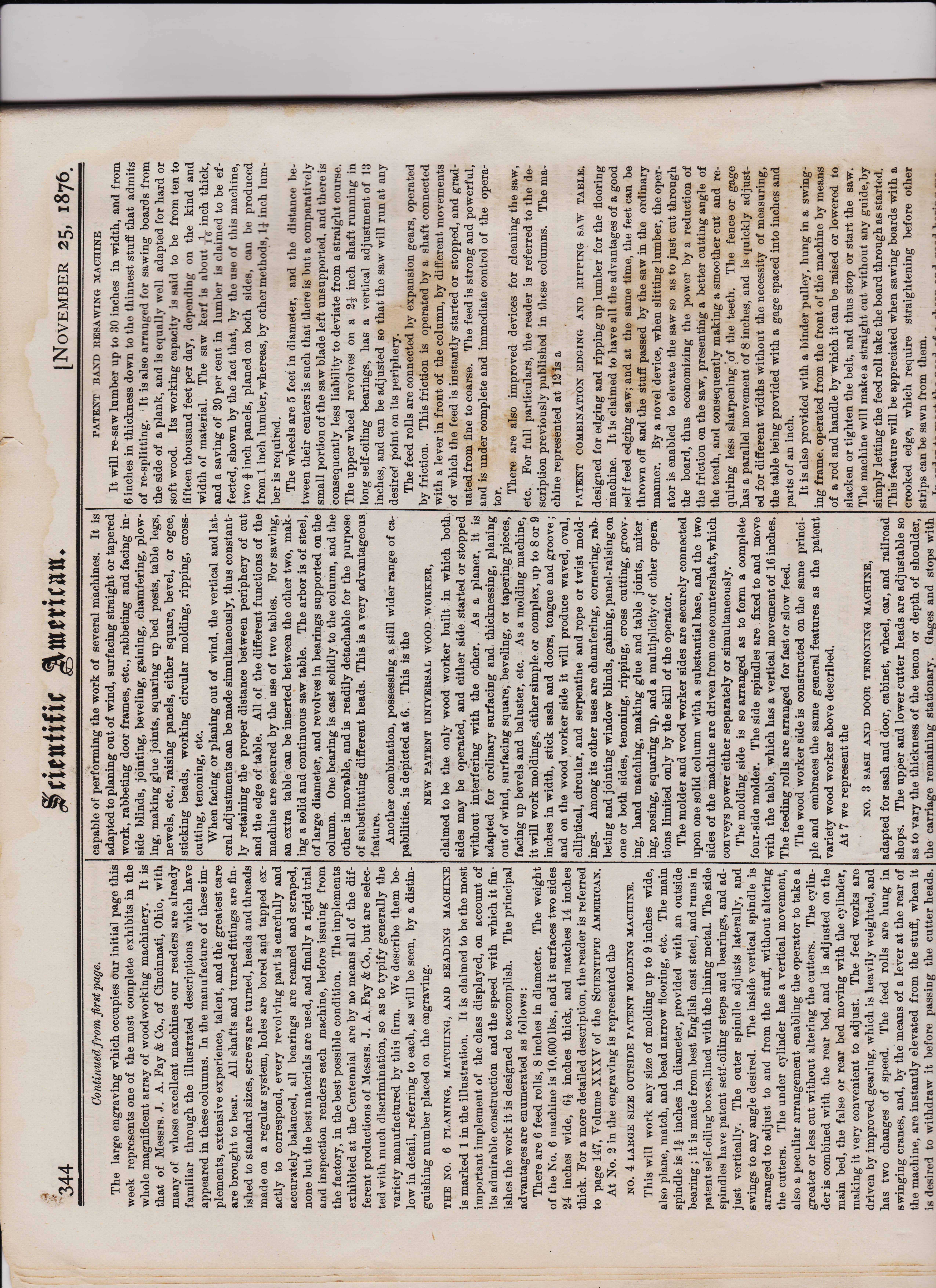
Continued from first page. The large engraving which occupies our initial page this week represents one of the most complete exhibits in the whole magnificent array of woodworking machinery. It is that of Messrs. J. A. Fay & Co., of Cincinnati, Ohio, with many of whose excellent machines our readers are already familiar through the illustrated descriptions which have appeared in these columns. In the manufacture of these im-plements, extensive experience, talent, and the greatest care are brought to bear. All shafts and turned fittings are fin-ished to standard sizes, screws are turned, heads and threads made on a regular system, holes are bored and tapped ex-actly to correspond, every revolving part is carefully and accurately balanced, all bearings are reamed and scraped, none but the best materials are used, and finally a rigid trial and inspection renders each machine, before issuing from the factory, in the best possible condition. The implements exhibited at the Centennial are by no means all of the dif-ferent productions of Messrs. J. A. Fay & Co., but are selec-ted with much discrimination, so as to typify generally the variety manufactured by this firm. We describe them be-low in detail, referring to each, as will be seen, by a distin-guishing number placed on the engraving. THE NO. 6 PLANING, MATCHING, AND BEADING MACHINE is marked 1 in the illustration. It is claimed to be the most important implement of the class displayed, on account of its admirable construction and the speed with which it fin-ishes the work it is designed to accomplish. The principal advantages are enumerated as follows : There are 6 feed rolls, 8 inches in diameter. The weight of the No. 6 machine is 10,600 lbs. , and it surfaces two sides 24 inches wide, 6+ inches thick, and matches 14 inches thick. For a more detailed description, the reader is referred to page 147,
Volume XXXV of the SCIENTIFIC AMERICAN. At No. 2 in the engraving is represented the NO. 4 LARGE SIZE OUTSIDE PATENT MOLDING MACHINE. This will work any size of molding up to 9 inches wide, also plane, match, and bead narrow flooring, etc. The main spindle is 1 inches in diameter, provided with an outside bearing ; it is made from best English cast steel, and runs in patent self-oiling boxes,lined with the lining metal. The side spindles have patent setf-oiling steps and bearings, and ad-j ust vertically. The outer spindle adjusts laterally, and swings to any angle desired. The inside vertical spindle is arranged to adjust to and from the stuff, without altering the cutters. The under cylinder has a vertical movement, also a peculiar arrangement enabling the operator to take a greater or less cut without altering the cutters. The cylin-der is combined with the rear bed, and is adjusted on the main bed, the false or rear bed moving with the cylinder, making it very convenient to adjust. The feed works are driven by improved gearing, which is heavily weighted, and has two changes of speed. The feed rolls are hung in swinging cranes, and, by the means of a lever at the rear of the machine, are instantly elevated from the stuff, when it is desired to withdraw it before passing the cutter heads. capable of performing the work of several machines. It is adapted to planing out of wind, surfacing straight or tapered work, rabbeting door frames, etc., rabbeting and facing in-side blinds, jointing, beveling, gaining, chamfering, plow-ing, making glue joints, squaring up bed posts, table legs, newels, etc., raising panels, either square, bevel, or ogee, sticking beads, working circular molding, ripping, cross-cutting, tenoning, etc. When facing or planing out of wind, the vertical and lat-eral adjustments can be made simultaneously, thus constant-ly retaining the proper distance between periphery of cut and the edge of table. All of the different functions of the machine are secured by the use of two tables. For sawing, an extra table can be inserted between the other two, mak-ing a solid and continuous saw table. The arbor is of steel, of large diameter, and revolves in bearings supported on the column. One bearing is cast solidly to the column, and the other is movable, and is readily detachable for the purpose of substituting different heads. This is a very advantageous feature. Another combination, possessing a still wider range of ca-pabilities, is depicted at 6. This is the
NEW PATENT UNIVERSAL WOOD WORKER, claimed to be the only wood worker built in which both sides may be operated, and either side started or stopped without interfering with the other. As a planer, it is adapted for ordinary surfacing and thicknessing, planing out of wind, surfacing square, beveling, or tapering pieces, facing up bevels and baluster, etc. As a molding machine, it will work moldings, either simple or complex, up to 8 or 9 inches in width, stick sash and doors, tongue and groove ; and on the wood worker side it will produce waved, oval, elliptical, circular, and serpentine and rope or twist mold-ings. Among its other uses are chamfering, cornering, rab-beting and jointing window blinds, gaining, panel-raising on one or both sides, tenoning, ripping, cross cutting, groov-ing, hand matching, making glue and table joints, miter ing, nosing, squaring up, and a multiplicity of other opera' tions limited only by the skill of the operator. The molder and wood worker sides are securely connected upon one solid column with a substantial base, and the two sides of the machine are driven from one countershaft,which conveys power either separately or simultaneously. The molding side is so arranged as to form a complete four-side molder. The side spindles are fixed to and move with the table, which has a vertical movement of 16 inches. The feeding rolls are arranged for fast or slow feed. The wood worker side is constructed on the same princi-ple and embraces the same general features as the patent variety wood worker above described. At 7 we represent the NO. 3
SASH AND DOOR TENONING MACHINE, adapted for sash and door, cabinet, wheel, car, and railroad shops. The upper and lower cutter heads are adjustable so as to vary the thickness of the tenon or depth of shoulder, the carriage remaining stationary. Gages and stops with
PATENT BAND RESAWING MACHINE It will re-saw lumber up to 30 inches in width, and from 6 inches in thickness down to the thinnest stuff that admits of re-splitting. It is also arranged for sawing boards from the side of a plank, and is equally well adapted for hard or soft wood. Its working capacity is said to be from ten to fifteen thousand feet per day, depending on the kind and width of material. The saw kerf is about T\I- inch thick, and a saving of 20 per cent in lumber is claimed to be ef-fected, shown by the fact that, by the use of this machine, two inch panels, planed on both sides, can be produced from 1 inch lumber, whereas, by other methods, I i rich lum-ber is required. The wheels are 5 feet in diameter, and the distance be-tween their centers is such that there is but a comparati vely small portion of the saw blade left unsupported, and there is consequently less liability to deviate from a straight course. The upper wheel revolves on a 2+ inch shaft running in long self-oiling bearings, has a vertical adjustment of 13 inches, and can be adjusted so that the saw will run at any desirea point on its periphery. The feed rolls are connected by expansion gears, operated by friction. This friction is operated by a shaft connected with a lever in front of the column, by different movements of which the feed is instantly started or stopped, and grad-uated from fine to coarse. The feed is strong and powerful, and is under complete and immediate control of the opera-tor. There are also improved devices for cleaning the saw, etc. For full particulars, the reader is referred to the de-scription previously published in these columns. The ma-chine represented at 12 is a
PATENT COMBINATION EDGING AND RIPPING SAW TABLE. designed for edging and ripping up lumber 'for the flooring machine. It is claimed to have all the advantages of a good self feed edging saw; and at the same time, the feet can be thrown off and the stuff passed by the saw in the ordinary manner. By a novel device, when slitting lumber, the oper-ator is enabled to elevate the saw so as to just cut through the board, thus economizing the power by a reduction of the friction on the saw, presenting a better cutting angle of the teeth, and consequently making a smoother cut and re-quiring less sharpening of the teeth. The fence or gage has a parallel movement of 8 inches, and is quickly adjust-ed for different widths without the necessity of measuring, the table being provided with a gage spaced into inches and parts of an inch. It is also provided with a binder pulley, hung in a swing-ing frame, operated from the front of the machine by means of a rod and handle by which it can be raised or lowered to slacken or tighten the belt, and thus stop or start the saw. The machine will make a straight cut without any guide,by simply letting the feed roll take the board through as started. This feature will be appreciated when sawing boards with a crooked edge, which require straightening before other strips can be sawn from them. T A.
also a peculiar arrangement enabling the operator to take a greater or less cut without altering the cutters. The cylin-der is combined with the rear bed, and is adjusted on the main bed, the false or rear bed moving with the cylinder, making it very convenient to adjust. The feed works are driven by improved gearing, which is heavily weighted, and has two changes of speed. The feed rolls are hung in swinging cranes, and, by the means of a lever at the rear of the machine, are instantly elevated from the stuff, when it is desired to withdraw it before passing the cutter heads. The bed drop is 13 inches. The machine is furnished with pressure bars, springs, steel wrenches, guides, and every thing needed for speedy adjustments. It is made to work either 3 or 4 sides, as may be desired, of 8, 9, and 10 inches wide or under.
THE NO. 2 INSIDE PATENT MOLDING MACHINE, WITH BEADING ATTACHMENT, is represented at 3. This machine will work moldings on one or both sides, 12 inches wide and under, and up to 5 inches in thickness, also plane, tongue, groove, and bead 12 inches wide. The cutters may be set at varying angles and are capable of sticking any style of molding, by using cutters on all four sides, thus equalizing the cut and utilizing the power. The under cylinder has a vertical adjustment, graduated to differ-ent thicknesses of cut while in motion; and by simple loos-ening one bolt, the pressure bar and stands can be swung en-tirely clear of the cylinder, giving free access to the cutters for purposes of sharpening or adjusting. A patent beading attachment upon the pressure bar, over the under cylinder, gages the depth of the bead from the surface of the board, thus securing an automatic adjustment of the beading shaft at all times. The upright spindles can be moved vertically or horizon-tally while in motion, the outer spindle to any angle de-sired. Devices are provided for preventing the possibility of movement after the heads are brought to the desired posi-tion; and there is a chip breaker for holding the fiber of the wood while the side cuts are being made. An equal pres-sure is maintained on the lumber being worked, regardless of any equalities in the thickness. The rolls are connected by expansion gearing, which allows the upper roll to adapt itself to the varying angles on irregularly sawn lumber. At 3 is represented the PATENT CARVING AND PANELING MACHINE, the object of which is to produce carvings and recessed or relieved panels on the surface of lumber, edge molding, or-namenting, fret and bracket work, etc. It is especially adapted for fine furniture, coffin and piano manufactories, etc. A hollow iron column gives an ample support for the cutter spindle and also for the table, which is adjusted and regulated to form the required depth of moldings or carvings by means of hand wheel and screw, and has sufficient ver-tical movement to admit of working stuff of four inches thick and under.
THE NO. 2 VARIETY WOOD WORKER is represented at 5. This is one of those remarkable tools I lit, LUIZ/11111g 1 VIM VA, IU11augeu 1 VI W. ZIA/ W 1 The wood worker side is constructed on the same princi-ple and embraces the same general features as the patent variety wood worker above described. At 7 we represent the
NO. 3 SASH AND DOOR TENONING MACHINE, adapted for sash and door, cabinet, wheel, car, and railroad shops. The upper and lower cutter heads are adjustable so as to vary the thickness of the tenon or depth of shoulder, the carriage remaining stationary. Gages and stops with the carriage render setting out unnecessary. The copes are raised and lowered with the cutter heads, but may be inde pendently set. Both cope and cutter head shafts are pro tected against endwise vibration. The upper cutter head is arranged to cut one shoulder of the tenon longer if desired, saw spurs are used in lieu of knife spurs, and the cutters operate with a drawing stroke. There is a binding pulley which keeps the belt right and self-adjusting, and the bon-net may be conveniently swung back out of the way to afford access to the cutters. The
ELLIS PATENT BLIND SLAT TENONING MACHINE, shown at 8, is adapted to any length or width of slat, work-ing both ends, cutting the shoulder and rounding the tenons simultaneously at one and at the same operation. The ma-chine, which has a hand feed, is provided with two adjusta-ble arbors and frames, carrying a set of circular saws for forming the shoulder and rounding the tenon. Connected to the arbor frames are revolving disks, into which the slat is inserted and rotated in contact with the saws or cutting tools. We are informed that it is capable of working 20,000 slats per day. At 9 is shown the
PATENT SELF-FEED BLIND SLAT TENONING MACHINE, which differs from the machine last described. It differs somewhat from the Ellis machine, as the slat is fed endwise through rotating chucks, the shoulder being pressed against an adjustable gage for regulating the length of slat. By the peculiar construction of the revolving cutting tools, two tenons are cut and divided with one cutter head, simulta-neously and at one operation. A pressure upon the treadle causes a rotation of the slat, and at the same time depresses the chucks, carrying the slat against the cutting tools, ena-bling them to form a perfect tenon on each end. It will work any length of slat from 11 inches up to 24 inches, and will make any size of tenon desired.
TWO PATENT BAND SAWING MACHINES are depicted in the engraving, one for ordinary curve saw-ing, the other (10) intended for the furniture, wagon, sash and door,and agricultural shops,etc. An important feature is the method of keeping 1 he saw at its proper tension, allow-ing at the same time some flexibility to the parts, to com-pensate for any sudden impact, and prevent breaking of the saws by buckling or friction upon the back or sides. There is also a shipper with frictional brake for arresting the saw motion, and the table is provided with irregular adjustment for bevel sawing. At 11 is represented a parts of an inch. It is also provided with a binder pulley, hung in a swing-ing frame, operated from the front of the machine by means of a rod and handle by which it can be raised or lowered to slacken or tighten the belt, and thus stop or start the saw. The machine will make a straight cut without any guide,by simply letting the feed roll take the board through as started. This feature will be appreciated when sawing boards with a crooked edge, which require straightening before other strips can be sawn from them. In order to meet the need of a cheap and good boring ma chine, for either straight or angular boring, the
UNIVERSAL HORIZONTAL BORING MACHINE, represented at 13, has been designed. The table is adjustable for boring at any desired upward or downward angle and the fence for any lateral angle. The traversing steel spindle is operated by means of a pow-erful jointed treadle, fitted with an improved step, which is provided with a steel point, forming a bearing for the end of the spindle, thus greatly reducing the wear, caused by the spindle pressing against a shoulder. The treadle has a weighted counterbalance, giving a quick return to the spin-dle. The spindle is fitted with cone pulley, with three changes of speed,and adjusting collars to graduate the depth of the hole to be bored. At 14 is shown a novel
PATENT BAND SAW SETTING AND FILING MACHINE, which, it is claimed, will set an ordinary band saw blade in three minutes, more accurately than can be done by hand in an hour. The saw being adjusted, the wheels are set far enough apart to straighten the blade, which is then pinched by a cam and wedges. The dies are set on the points of the teeth,and are adjusted with set screws on top. This sets the points over without bending them at the roots, pre-venting the warping of the saw which is liable to occur in setting by hand. Lastly at 15 we illustrate a
HAND AND POWER FEED SURFACE PLANING MACHINE. This is provided with steel-lipped cylinder, pressure bar, shaving bonnet, and adjustable tables. It will surface 24 inches wide up to 6 inches in thickness. This completes our list of machines, which, as embodi-ments of the new and ingenious devices, and as showing ad-mirable adaptation to their several purposes, may justly be regarded as representing the best work of both inventor and manufacturer. It is hardly necessary to add that their su-perior qualities are appreciated in foreign countries as well as in our own, and that the large trade which their maker now control, with Japan, Australia, South America, Enf land, New Zealand, and elsewhere, is one which reflect great credit upon our home industries. The machines have received the largest premiums at local fairs in this country, a medal at the Vienna Exposition, 'a medal for excel-silence and superiority at the late Chilian Exposition, Santia-go, Chili, South America, and also medal of honor and spe-cial commendatory reports from the Centennial jurors of awards.
Scientific-American-Nov-25-1876-p339-bot.jpeg
SCIENTIFIC AMERICAN pg 343 NOVEMBER 25, 1876.
pg 344 test test NOVEMBER 25, 1876. NOVFMBER 25, 1876.pic 9 ---page 344 Scientifir American.
Continued from first page. The large engraving which occupies our initial page this week represents one of the most complete exhibits in the whole magnificent array of woodworking machinery. It is that of Messrs. J. A. Fay & Co., of Cincinnati, Ohio, with many of whose excellent machines our readers are already familiar through the illustrated descriptions which have appeared in these columns. In the manufacture of these im-plements, extensive experience, talent, and the greatest care are brought to bear. All shafts and turned fittings are fin-ished to standard sizes, screws are turned, heads and threads made on a regular system, holes are bored and tapped ex-actly to correspond, every revolving part is carefully and accurately balanced, all bearings are reamed and scraped, none but the best materials are used, and finally a rigid trial and inspection renders each machine, before issuing from the factory, in the best possible condition. The implements exhibited at the Centennial are by no means all of the dif-ferent productions of Messrs. J. A. Fay & Co., but are selec-ted with much discrimination, so as to typify generally the variety manufactured by this firm. We describe them be-low in detail, referring to each, as will be seen, by a distin-guishing number placed on the engraving. THE NO. 6 PLANING, MATCHING, AND BEADING MACHINE is marked 1 in the illustration. It is claimed to be the most important implement of the class displayed, on account of its admirable construction and the speed with which it fin-ishes the work it is designed to accomplish. The principal advantages are enumerated as follows : There are 6 feed rolls, 8 inches in diameter. The weight of the No. 6 machine is 10,600 lbs. , and it surfaces two sides 24 inches wide, 6+ inches thick, and matches 14 inches thick. For a more detailed description, the reader is referred to page 147,
Volume XXXV of the SCIENTIFIC AMERICAN. At No. 2 in the engraving is represented the NO. 4 LARGE SIZE OUTSIDE PATENT MOLDING MACHINE. This will work any size of molding up to 9 inches wide, also plane, match, and bead narrow flooring, etc. The main spindle is 1 inches in diameter, provided with an outside bearing ; it is made from best English cast steel, and runs in patent self-oiling boxes,lined with the lining metal. The side spindles have patent setf-oiling steps and bearings, and ad-j ust vertically. The outer spindle adjusts laterally, and swings to any angle desired. The inside vertical spindle is arranged to adjust to and from the stuff, without altering the cutters. The under cylinder has a vertical movement, also a peculiar arrangement enabling the operator to take a greater or less cut without altering the cutters. The cylin-der is combined with the rear bed, and is adjusted on the main bed, the false or rear bed moving with the cylinder, making it very convenient to adjust. The feed works are driven by improved gearing, which is heavily weighted, and has two changes of speed. The feed rolls are hung in swinging cranes, and, by the means of a lever at the rear of the machine, are instantly elevated from the stuff, when it is desired to withdraw it before passing the cutter heads. capable of performing the work of several machines. It is adapted to planing out of wind, surfacing straight or tapered work, rabbeting door frames, etc., rabbeting and facing in-side blinds, jointing, beveling, gaining, chamfering, plow-ing, making glue joints, squaring up bed posts, table legs, newels, etc., raising panels, either square, bevel, or ogee, sticking beads, working circular molding, ripping, cross-cutting, tenoning, etc. When facing or planing out of wind, the vertical and lat-eral adjustments can be made simultaneously, thus constant-ly retaining the proper distance between periphery of cut and the edge of table. All of the different functions of the machine are secured by the use of two tables. For sawing, an extra table can be inserted between the other two, mak-ing a solid and continuous saw table. The arbor is of steel, of large diameter, and revolves in bearings supported on the column. One bearing is cast solidly to the column, and the other is movable, and is readily detachable for the purpose of substituting different heads. This is a very advantageous feature. Another combination, possessing a still wider range of ca-pabilities, is depicted at 6. This is the
NEW PATENT UNIVERSAL WOOD WORKER, claimed to be the only wood worker built in which both sides may be operated, and either side started or stopped without interfering with the other. As a planer, it is adapted for ordinary surfacing and thicknessing, planing out of wind, surfacing square, beveling, or tapering pieces, facing up bevels and baluster, etc. As a molding machine, it will work moldings, either simple or complex, up to 8 or 9 inches in width, stick sash and doors, tongue and groove ; and on the wood worker side it will produce waved, oval, elliptical, circular, and serpentine and rope or twist mold-ings. Among its other uses are chamfering, cornering, rab-beting and jointing window blinds, gaining, panel-raising on one or both sides, tenoning, ripping, cross cutting, groov-ing, hand matching, making glue and table joints, miter ing, nosing, squaring up, and a multiplicity of other opera' tions limited only by the skill of the operator. The molder and wood worker sides are securely connected upon one solid column with a substantial base, and the two sides of the machine are driven from one countershaft,which conveys power either separately or simultaneously. The molding side is so arranged as to form a complete four-side molder. The side spindles are fixed to and move with the table, which has a vertical movement of 16 inches. The feeding rolls are arranged for fast or slow feed. The wood worker side is constructed on the same princi-ple and embraces the same general features as the patent variety wood worker above described. At 7 we represent the NO. 3
SASH AND DOOR TENONING MACHINE, adapted for sash and door, cabinet, wheel, car, and railroad shops. The upper and lower cutter heads are adjustable so as to vary the thickness of the tenon or depth of shoulder, the carriage remaining stationary. Gages and stops with
PATENT BAND RESAWING MACHINE It will re-saw lumber up to 30 inches in width, and from 6 inches in thickness down to the thinnest stuff that admits of re-splitting. It is also arranged for sawing boards from the side of a plank, and is equally well adapted for hard or soft wood. Its working capacity is said to be from ten to fifteen thousand feet per day, depending on the kind and width of material. The saw kerf is about T\I- inch thick, and a saving of 20 per cent in lumber is claimed to be ef-fected, shown by the fact that, by the use of this machine, two inch panels, planed on both sides, can be produced from 1 inch lumber, whereas, by other methods, I i rich lum-ber is required. The wheels are 5 feet in diameter, and the distance be-tween their centers is such that there is but a comparati vely small portion of the saw blade left unsupported, and there is consequently less liability to deviate from a straight course. The upper wheel revolves on a 2+ inch shaft running in long self-oiling bearings, has a vertical adjustment of 13 inches, and can be adjusted so that the saw will run at any desirea point on its periphery. The feed rolls are connected by expansion gears, operated by friction. This friction is operated by a shaft connected with a lever in front of the column, by different movements of which the feed is instantly started or stopped, and grad-uated from fine to coarse. The feed is strong and powerful, and is under complete and immediate control of the opera-tor. There are also improved devices for cleaning the saw, etc. For full particulars, the reader is referred to the de-scription previously published in these columns. The ma-chine represented at 12 is a
PATENT COMBINATION EDGING AND RIPPING SAW TABLE. designed for edging and ripping up lumber 'for the flooring machine. It is claimed to have all the advantages of a good self feed edging saw; and at the same time, the feet can be thrown off and the stuff passed by the saw in the ordinary manner. By a novel device, when slitting lumber, the oper-ator is enabled to elevate the saw so as to just cut through the board, thus economizing the power by a reduction of the friction on the saw, presenting a better cutting angle of the teeth, and consequently making a smoother cut and re-quiring less sharpening of the teeth. The fence or gage has a parallel movement of 8 inches, and is quickly adjust-ed for different widths without the necessity of measuring, the table being provided with a gage spaced into inches and parts of an inch. It is also provided with a binder pulley, hung in a swing-ing frame, operated from the front of the machine by means of a rod and handle by which it can be raised or lowered to slacken or tighten the belt, and thus stop or start the saw. The machine will make a straight cut without any guide,by simply letting the feed roll take the board through as started. This feature will be appreciated when sawing boards with a crooked edge, which require straightening before other strips can be sawn from them. T A.
also a peculiar arrangement enabling the operator to take a greater or less cut without altering the cutters. The cylin-der is combined with the rear bed, and is adjusted on the main bed, the false or rear bed moving with the cylinder, making it very convenient to adjust. The feed works are driven by improved gearing, which is heavily weighted, and has two changes of speed. The feed rolls are hung in swinging cranes, and, by the means of a lever at the rear of the machine, are instantly elevated from the stuff, when it is desired to withdraw it before passing the cutter heads. The bed drop is 13 inches. The machine is furnished with pressure bars, springs, steel wrenches, guides, and every thing needed for speedy adjustments. It is made to work either 3 or 4 sides, as may be desired, of 8, 9, and 10 inches wide or under.
THE NO. 2 INSIDE PATENT MOLDING MACHINE, WITH BEADING ATTACHMENT, is represented at 3. This machine will work moldings on one or both sides, 12 inches wide and under, and up to 5 inches in thickness, also plane, tongue, groove, and bead 12 inches wide. The cutters may be set at varying angles and are capable of sticking any style of molding, by using cutters on all four sides, thus equalizing the cut and utilizing the power. The under cylinder has a vertical adjustment, graduated to differ-ent thicknesses of cut while in motion; and by simple loos-ening one bolt, the pressure bar and stands can be swung en-tirely clear of the cylinder, giving free access to the cutters for purposes of sharpening or adjusting. A patent beading attachment upon the pressure bar, over the under cylinder, gages the depth of the bead from the surface of the board, thus securing an automatic adjustment of the beading shaft at all times. The upright spindles can be moved vertically or horizon-tally while in motion, the outer spindle to any angle de-sired. Devices are provided for preventing the possibility of movement after the heads are brought to the desired posi-tion; and there is a chip breaker for holding the fiber of the wood while the side cuts are being made. An equal pres-sure is maintained on the lumber being worked, regardless of any equalities in the thickness. The rolls are connected by expansion gearing, which allows the upper roll to adapt itself to the varying angles on irregularly sawn lumber. At 3 is represented the PATENT CARVING AND PANELING MACHINE, the object of which is to produce carvings and recessed or relieved panels on the surface of lumber, edge molding, or-namenting, fret and bracket work, etc. It is especially adapted for fine furniture, coffin and piano manufactories, etc. A hollow iron column gives an ample support for the cutter spindle and also for the table, which is adjusted and regulated to form the required depth of moldings or carvings by means of hand wheel and screw, and has sufficient ver-tical movement to admit of working stuff of four inches thick and under.
THE NO. 2 VARIETY WOOD WORKER is represented at 5. This is one of those remarkable tools I lit, LUIZ/11111g 1 VIM VA, IU11augeu 1 VI W. ZIA/ W 1 The wood worker side is constructed on the same princi-ple and embraces the same general features as the patent variety wood worker above described. At 7 we represent the
NO. 3 SASH AND DOOR TENONING MACHINE, adapted for sash and door, cabinet, wheel, car, and railroad shops. The upper and lower cutter heads are adjustable so as to vary the thickness of the tenon or depth of shoulder, the carriage remaining stationary. Gages and stops with the carriage render setting out unnecessary. The copes are raised and lowered with the cutter heads, but may be inde pendently set. Both cope and cutter head shafts are pro tected against endwise vibration. The upper cutter head is arranged to cut one shoulder of the tenon longer if desired, saw spurs are used in lieu of knife spurs, and the cutters operate with a drawing stroke. There is a binding pulley which keeps the belt right and self-adjusting, and the bon-net may be conveniently swung back out of the way to afford access to the cutters. The
ELLIS PATENT BLIND SLAT TENONING MACHINE, shown at 8, is adapted to any length or width of slat, work-ing both ends, cutting the shoulder and rounding the tenons simultaneously at one and at the same operation. The ma-chine, which has a hand feed, is provided with two adjusta-ble arbors and frames, carrying a set of circular saws for forming the shoulder and rounding the tenon. Connected to the arbor frames are revolving disks, into which the slat is inserted and rotated in contact with the saws or cutting tools. We are informed that it is capable of working 20,000 slats per day. At 9 is shown the
PATENT SELF-FEED BLIND SLAT TENONING MACHINE, which differs from the machine last described. It differs somewhat from the Ellis machine, as the slat is fed endwise through rotating chucks, the shoulder being pressed against an adjustable gage for regulating the length of slat. By the peculiar construction of the revolving cutting tools, two tenons are cut and divided with one cutter head, simulta-neously and at one operation. A pressure upon the treadle causes a rotation of the slat, and at the same time depresses the chucks, carrying the slat against the cutting tools, ena-bling them to form a perfect tenon on each end. It will work any length of slat from 11 inches up to 24 inches, and will make any size of tenon desired.
TWO PATENT BAND SAWING MACHINES are depicted in the engraving, one for ordinary curve saw-ing, the other (10) intended for the furniture, wagon, sash and door,and agricultural shops,etc. An important feature is the method of keeping 1 he saw at its proper tension, allow-ing at the same time some flexibility to the parts, to com-pensate for any sudden impact, and prevent breaking of the saws by buckling or friction upon the back or sides. There is also a shipper with frictional brake for arresting the saw motion, and the table is provided with irregular adjustment for bevel sawing. At 11 is represented a parts of an inch. It is also provided with a binder pulley, hung in a swing-ing frame, operated from the front of the machine by means of a rod and handle by which it can be raised or lowered to slacken or tighten the belt, and thus stop or start the saw. The machine will make a straight cut without any guide,by simply letting the feed roll take the board through as started. This feature will be appreciated when sawing boards with a crooked edge, which require straightening before other strips can be sawn from them. In order to meet the need of a cheap and good boring ma chine, for either straight or angular boring, the
UNIVERSAL HORIZONTAL BORING MACHINE, represented at 13, has been designed. The table is adjustable for boring at any desired upward or downward angle and the fence for any lateral angle. The traversing steel spindle is operated by means of a pow-erful jointed treadle, fitted with an improved step, which is provided with a steel point, forming a bearing for the end of the spindle, thus greatly reducing the wear, caused by the spindle pressing against a shoulder. The treadle has a weighted counterbalance, giving a quick return to the spin-dle. The spindle is fitted with cone pulley, with three changes of speed,and adjusting collars to graduate the depth of the hole to be bored. At 14 is shown a novel
PATENT BAND SAW SETTING AND FILING MACHINE, which, it is claimed, will set an ordinary band saw blade in three minutes, more accurately than can be done by hand in an hour. The saw being adjusted, the wheels are set far enough apart to straighten the blade, which is then pinched by a cam and wedges. The dies are set on the points of the teeth,and are adjusted with set screws on top. This sets the points over without bending them at the roots, pre-venting the warping of the saw which is liable to occur in setting by hand. Lastly at 15 we illustrate a
HAND AND POWER FEED SURFACE PLANING MACHINE. This is provided with steel-lipped cylinder, pressure bar, shaving bonnet, and adjustable tables. It will surface 24 inches wide up to 6 inches in thickness. This completes our list of machines, which, as embodi-ments of the new and ingenious devices, and as showing ad-mirable adaptation to their several purposes, may justly be regarded as representing the best work of both inventor and manufacturer. It is hardly necessary to add that their su-perior qualities are appreciated in foreign countries as well as in our own, and that the large trade which their maker now control, with Japan, Australia, South America, Enf land, New Zealand, and elsewhere, is one which reflect great credit upon our home industries. The machines have received the largest premiums at local fairs in this country, a medal at the Vienna Exposition, 'a medal for excel-silence and superiority at the late Chilian Exposition, Santia-go, Chili, South America, and also medal of honor and spe-cial commendatory reports from the Centennial jurors of awards.
SCIENTIFIC AMERICAN pg 345 NOVEMBER 25, 1876.
pg 345 NOVEMBER 25, 1876. NOVFMBER 25, 1876. pic 10 ---page 345 Scientific American.
NOVEMBER 25, 1876. 345 CENTENNIAL NOTES. TIIE FRENCH POTTERY DISPLAY. France,
THE AWARDS FOR THE LYALL LOOMS.
SCIENTIFIC AMERICAN pg 346 NOVEMBER 25, 1876.
pg 345 test test NOVEMBER 25, 1876. NOVFMBER 25, 1876. pic 10 -test again--page 346 Scientific American.
NOVEMBER 25, 1876. pg 346 ,
A WEEKLY JOURNAL OF PRACTICAL INFORMATION, ART, SCIENCE, MECHANICS, CHEMISTRY, AND MANUFACTURES. Vol. xxx -No . 22.1 NEW SERIES. NEW YORK, NOVEMBER 25, 1876.
3.20 per Annum. POSTAGE PRE-PAID .
pg 347- NOVEMBER 25, 1876. pg 347 test --NOVEMBER 25, 1876. pg 347 ffritutifir (anterican. uglinto and geroonal, The Clutruc for Ins6rtion under this head is One Dol-lar a Line for each insertion. If the Notice ex-ceeds Pour .Mmes, One Dollar and a Half per Lime will he charged. I f you want a complete collection of the best ITO 1,1,14 and trade hints published in Scientific A Ille 1'1 ea 11 ror past, 10 years, send $1.50 to H. N. Munn, 37 lark low, New York, for Wrinkles and Recipes. 250 pages, splen-didly illustrated Agricultural Implements and Industrial Machin-ery for Export and Domestic Use. R.H.Allen & Co., N.Y. Town and Village Hand Fire Engines, with hose carriage and fittings, only $350. Send for cuts and full nformation. S. C. Forsaith & Co., Manchester, N. H. See advertisement of Industrial Mfg. Co., p. 349. For durability and economy, use Blake's Belt Studs to fasten Belts. Greene, Tweed & Co., 18 Park Place, New York. Split-Pulleys and Split-Collars of same price, strength and appearance as Whole-Pulleys and Whole-Collars. Yoc om & Son, Drinker St., below 147 North Second St., Philadelphia, Pa. To Lease—The largest portion of the building corner Canal, Center, and Walker Sts., now occupied as a Billiard Manufactory and Sales Room. See adver-tisement in another column. The Cabinet Machine—A Complete Wood Work-er. M. R. Conway, 222 W. 2d St., Cincinnati, Ohio. The Gatling Gun received the only medal and award given for machine guns at the Centennial Exhibi-tion. For information regarding this gun, address Gat-ing* Gun Co., Hartford, Conn., U. S. A. Journal of Microscopy—For Amateurs. Plain, practical, reliable. 50 cent s per year. Specimens free. Address Box 4875, New York. For Sale—Shop Rights to every Tool Builder and manufacturer for Bean's Patent Friction Pulley Coun-tershaft. D. Frisbie & Co., New Haven, Conn. Superior Lace Leather, all Sizes, Cheap. Hooks and Couplings for fiat and round Belts. Send for cata-logue. C. W. Arm,. 148 North 3d St., Philadelphia, Pa. Magic Lanterns, Stereopticons, for Parlor En-tertainments and Public Exhibitions. Pays well on small capital. 74 Page Catalogue free. Centennial Medal and Diploma awarded. McAllister, 49 Nassau St., N. Y. Noiseless Exhaust Nozzles for Exhaust Pipes and Pop Valves. T. Shaw, 915 Ridge Av., Phila., Pa. Fire Hose,Rubber Lined Linen, also Cotton,finest quality. Eureka Fire Hose Co. , 13 Barclay St. ,N ew York. Shingle, Heading and Stave Machine. See ad-vertisement of Trevor & Co., Lockport, N. Y. The Scientific American Supplement—Any de-sired back number can be had for 10 cents, at this office, or almost any news store. To stop leaks in boiler tubes, use Quinn's Pat-ent Ferrules. Address S. M. Co , So. Newmarket,N.H. Water, Gas, and Steam Pipe, Wrought Iron. Send for prices. Bailey, Farrell & Co., Pittsburgh, Pa. For Solid Wrought-iron Beams, etc., see adver-tisement. Address Union Iron Mills, Pittsburgh, Pa. for lithograph, &c. Solid Emery Vulcanite Wheels—The Solid Orig-inal Emery Wheel—other kinds imitations and inferior. Caution.—Our name is stamped in full on all our best Standard Belting, Packing, and Hose. Buy that only. The best is the cheapest. New York Belting and Pack-nig Company, 37 and 38 Park Row, New York. roo new and second hand machines at low prices, (1) W. H. L. asks : Does a person, in lifting one wheel of a 4-wheeled wagon off the ground, lift more or less than a quarter of the whole weight ? A. More than a quarter if the vehicle Is rigid and the load equally distributed. (2) A. Y. asks : Is there any practical way of leveling without a theodolite ? A. You can construct an instrument with an ordinary build-er's level, that will enable you to get the hight. As such matters are discussed in special treatises, and would occupy too much space for these col-umns, we must refer you to some good book on the subject. There is a cheap level in the mar-ket, which is accompanied by full directions for use. (3) A. C. F. asks : What is the proper speed for grindstones, wet and dry? A. Circumferen-tial velocity, 1,800 to 2,000 feet per minute. I have a 10 horse power locomotive boiler ; it will hardly make steam enough for a 10 horse power engine. Would it be practicable to wall in the boiler and form an arch over the top, ar-ranging it to lead the heat (after leaving the flues) under the boiler towards the firebox, along the side of the firebox toward the front, then up and over the top of the boiler, back to rear end, and up the stack ? A. If you have a strong draft,you may gain something by the change. (4) T. P. F. asks : If two launches were built, one 30 and one 40 feet long, the same in every particular except length, which would run the fastest ? A. The first. (5) B. P. R. asks : 1. In a hot blast or air-tight steam boiler furnace, which is the best way to supply the air, under the grates or on top of the burning coal ? A. Under the grates. 2. How many lbs. steam to the square inch will a boiler 24 feet long by 40 inches diameter, of % inch iron, stand with safety ? A. About 60 lbs. 3. What dimensions of smoke stack ought I to have for the boiler, with two flues, each 14 inches in diameter? A. The cross section of the chimney should not be less than about of the grate sur-face. (6) J. S. C. asks : Is the statement that a body will weigh less at the equator than at the poles based on an actual test by weighing, or is it theoretical ? A. Based on actual test. (7) C. F. S. asks : 1. How large a boat will a boiler 44 inches high and 20 inches in diameter, and an engine with 3A inches stroke and about *6 inches bore, drive, and at what speed ? A.The machine will be suitable for a boat from 18 to 30 feet long. 2. What size of wheel and what pitch should I use ? A. Use one 20 or 24 inches in di-ameter with 3 feet pitch. Where does ice form in freezing, on top or at bottom of the water ? A. You can probably settle the matter to your satisfaction by observa-tions on a pond in which ice forms. First there will be a thin sheet of ice, which gradually thick-ens on the under side. (8) J. K. asks : Why will not iodide of po-tassium form in large crystals when made accord-ing to United States Pharmacopoeia ? A. In or-der to obtain good crystals of K I, it is necessary paring the solution is a good one; the trouble doubtless arises from the inefficient manner of preparing the articles. Different metals require different treatments. As a rule, the first thing to be done is to remove the greasy films with which most objects are covered ; this is effected by boil-ing and rubbing in a solution of caustic soda, made by boiling about 2 lbs. of common soda crystals with milk of lime, produced by slacking % lb. of quicklime with hot water, and well stir-ring. After this alkaline bath, the objects should be washed in several waters or in a running stream. They are next cleaned in acids, again washed, and then transferred to the depositing solution. Copper, brass, and German silver arti-cles should be immersed in a pickle composed of water 100 parts, oil of vitriol 100 parts, nitric acid (specific gravity 1•3). 50 parts, hydrochloric acid 2 parts. It is well also to coat the surface with a thin film of mercury. This is effected by means of a solution of 1 oz. mercury in sufficient nitric acid, with three times the quantity of water, diluted to one gallon ; there will form a gray or blackish deposit over the surface, which, on brushing softly, gives place to a brilliant coat-ing of mercury ; the object should be trans-ferred to the depositing cell the instant this is ob-tained. (14) J. McJ. asks : What will remove dried collodion from white cotton, without injuring the fabric ? If there is anything that will decompose it, it will be preferable to a solvent. A. Try steeping the cloth in cold water,and then rubbing it together so as to break up the films. (15) A. C. says : How thick should the cop-per and zinc plates be, and of what thickness should the wire be, of the galvanic battery men-tioned on p. 234, vol. 34 ? A. The plates may be made of any convenient thickness. No. 14 or 16 copper wire is used for the connections. 2. How should the zinc be suspended? A. From a wood-en or.metallic frame resting on the top of the jar. (16) G. B. McC. asks : Is it possible for the water to be carried out of the boiler through the pump ? We were sawing with a portable steam mill, and shut down at night with the usual amount of water. In the morning there was no water in the boiler, and we had to fill her up through the safety valve. There is a check valve on the feed pipe close to where the pipe connects with the boiler. A. It would not be possible, if the check valve were tight, which, judging from your account, might not have been the case. (17) A. H. asks : 1. Please give me full di-rections for making a good condenser for an in-duction coil. A. Cut tinfoil up into sheets of the desired size, and make of them two piles like the leaves of a book, one pile containing one more sheet than the other. Upon the extreme end of each of these piles place a tinned wire or strip of metal, and by means of a soldering iron run all the edges together so as to make a perfect metallic connection. Cut sheets of paper large enough to allow a margin of at least an inch round three sides of the foil. The paper should be thin, not highly glazed, and should show no 347 making some varieties of vitrified wares etc.—A. E.—It is augite, and contains some oxide of iron. —W. E. T.—They are both iron pyrites, and con-tain no precious metal.--N. V. C.—It is brown coal. COMMUNICATIONS RECEIVED. The Editor of the SCIENTIFIC AMERICAN ac-knowledges, with much pleasure, the receipt of original papers and contributions upon the follow-ing subjects : On the Centennial. Awards. By G. B. On Sound. By J. A. F. On Foul Air in Wells. By M. B. O'N. On the Moon. By J. D. On Cutting Speeds. By T. J. B. On Trisecting an Angle. By J. McM. On Smoky Chimneys. By F. G. W. Also inquiries and answers from the following : B. D.—G. B. P.—L. H. E. HINTS TO CORRESPONDENTS. Correspondents whose inquiries fail to appear should repeat them. If not then published, they may conclude that, for good reasons, the Editor declines them. The address of the writer should always be given. Enquiries relating to patents, or to the patenta-bility of inventions, assignments, etc., will not be published here. All such questions, when initials only are given, are thrown into the waste basket, as it would fill half of our paper to print them all ; but we generally take pleasure in answering briefly by mail, if the writer's address is given. Hundreds of inquiries analogous to the following are sent : " Who sells paraffin ? Who sells gutta percha ? Who sells crude India rubber ? Who sells proprietary stamps ? Who sells the best as-tronomical telescopes ? Whose is the best ane-roid barometer ?" All such personal inquiries are printed, as will be observed, in the column of " Business and Personal." which is specially set apart for that purpose, subject to the charge mentioned at the head of that column. Almost any desired information can in this way be expo-tiously obtained. [OFFICIAL.] INDEX OF INVENTIONS FOR WHICH Letters Patent of the United States were Granted in the Week Ending October 17, 1876, AND EACH BEARING THAT DATE. [Those marked (r) are reissued patents.] A complete copy of any patent in the annexed list, including both the specifications and drawings, will be furnished from this office for one dollar. in ordering, please state the number and date of the patent desired, and remit to Munn &Co., 37 Park Row, New York city. Adding machine, J. H. Mears 183, 409 Advertising ribbon reel, H. J. Rice 183,480 Agricultural steamer, R. W. ltulllYson 183,331 ==========================================================================================cut Ferrules. Address B. M. Co , So. Nowmarket,N.H. Water, Gas, and Steam Pipe, Wrought Iron. Send for prices. Bailey, Farrell & Co., Pittsburgh, Pa. For Solid Wrought-iron Beams, etc., see adver-tisement. Address Union Iron Mills, Pittsburgh, Pa. for lithograph, &c. Solid Emery Vulcanite Wheels-The Solid Orig-inal Emery Wheel-other kinds imitations and inferior. Caution.-Our name is stamped in full on all our best Standard Belting, Packing, and Hose. Buy that only. The best is the cheapest. New York Belting and Pack-.ng Company, 37 and 38 Park Row, New York. 500 new and second hand machines at low prices, fully described in printed lists. Send stamp, stating just what you want. S. C. Forsaith & Co. , Manchester, N,il. Hand Fire Engines, Lift and Force Pumps for fire and all other purposes. Address Rumsey & Co., Seneca Falls, N. Y., U . S. A. More than Ten Thousand Crank Shafts made by Chester Steel Castings Co., now running ; 8 years' con-stant use prove them stronger and more durable than wrought iron. See advertisement, page 349. See Boult's. Paneling, Moulding, and Dovetailing Machine at Centennial, B. 8-55. Send for pamphlet and sample of work. B. C. Mach'y Co., Battle Creek, Mich. M. Shaw, Manufacturer of Insulated Wire for galvanic and telegraph purposes, &c .,259 W .27th St., N.Y. F. C. Beach & Co., makers of the Tom Thumb Telegraph and other electrical machines, have removed to 530 Water Street, New York. Safety Linen Hose for Factories, 1 to 3 inches, at educed rates. Greene, Tweed & Co . ,18 Park Place,N. Y. Hyatt & Co.'s Varnishes and Japans, as to price, color, purity, and durability, are cheaper by comparison than any others extant. 246 Grand st.,N. Y. Fac tory, Ne w-ark, N. J. Send for circular and descriptive price list. Power & Foot Presses & all Fruit-can Tools. Fer-racute Wks. , Bridgeton, N.J. & C. 27, Mchy. Hall,Cent'1. For Sohd Emery Wheels and Machinery, send to the Union Stone Co., Boston, Mass., for circular. For best Presses, Dies, and Fruit Can Tools, Bliss & Williams, cor. of Plymouth and Jay, Brooklyn, N. Y. Steel Castings, from one lb. to five thousand lbs. Invaluable for strength and durability. Circulars free. Pittsburgh Steel Casting Co., Pittsburgh, Pa. Hydraulic Presses and Jacks, new and second nand. Lathes and Machinery for Polishing and Buffing metals. E. Lyon, 470 Grand Street, New York. Diamond Toois-J. Dickinson, 64 Nassau St., N. Y. Slide Rest for $8 to fit any lathe. Goodnow & Wightman, 23 Cornhill, Boston, Mass. "Dead Stroke" Power Hammers-recently great-ly improved, increasing cost over 10 per cent. Prices re-duced over 20 per cent. Hull & Belden Co. , Danbury,Ct. The " Abbe" Bolt Forging Machines and the .• Palmer" Power Hammers a specialty. Send for re-duced price lists S.C.Forsaith & Co., Manchester,N..EI. A. J. can polish starched linen goods by roilowing the directions on p. 203, vol. 31.-C. W. will find a description of a calcium light on p. Mill, vol. 30.-C. K. R, will find directions for ma-king friction matches on p. 75, vol. 29.-C. F. will will ilnd directions for hardening millpicks on p. 170, vol. 25 -M. W. can make vinegar by the pro-cess demeribed on p. 106, vol. 32.-A. B. R., C. W., 11. 1,., .1. K., .1. C. M., E. T. H., F. W., and others, who I0 4k 104 to recommend books on industrial and scientific mil Weill, should address the booksellers who advertise in our columns, all of whom are trustworthy firms, for catalogues. should I use ? A. Use one 20 or 24 inches in di-ameter with 3 feet pitch. Where does ice form in freezing, on top or at bottom of the water ? A. You can probably settle the matter to your satisfaction by observa-tions on a pond in which ice forms. First there will be a thin sheet of ice, which gradually thick-ens on the under side. (8) J. K. asks : Why will not iodide of po-tassium form in large crystals when made accord-ing to United States Pharmacopoeia? A. In or-der to obtain good crystals of K I, it is necessary that the crystalization should proceed as slowly as possible in a cool place, and under a good va-cuum. The best results are obtained when large quantities of the materials are operated upon at once. The solution of the iodide should be as neutral as possible. (9) M. asks : 1. Is the common commer cial potash in solution a good fertilizer for a grape vine when applied to the soil about its roots? If so, of what strength should it be used ? A. We would not recommend the use of potash. 2. Are ground or pulverized bones good for the same purpose ? A. The finely ground bones mixed with soil or peat make a very desirable manure. It would be better, however, to treat the ground bones with about one third the weight of oil of vitriol (specific gravity 1•70) in order to obtain the soluble superphosphate. The acid should be di-luted with about 2 parts of water, and well stirred in with the bone dust; it should then be al-lowed to stand for about 12 hours, when enough loam should be stirred in to absorb all the liquid. This is one of the best manures known. 3. If these articles were applied to a loamy or porous soil, situated 10 feet from a well of water, would there be any danger of contamination to the wa-ter ? A. No. (10) E. M. L. asks : In cutting up tortoise-shell, a lot of small scraps are made. How can they be worked up into a solid mass, by dissol-ving, or otherwise? A. The larger scraps might possibly be utilized for small inlaid work. Send us a few of the scraps and we may possibly be able to suggest some other application. (11) W. S. C. asks : What produces the phosphorescent light known as fox fire? A. We do not recognize the name, but suppose you refer to the strongly phosphorescent solution of phos-phorus in hot olive oil. Bisulphide of carbon or one of the essential oils may be made to replace the olive oil as the solvent. It would, perhaps, be well to state that the employment of the bisul-phide solution of phosphorus is liable, when the liquid is in contact with the air, to produce spon-taneous combustion. (12) S. W. J. asks : What is a simple and harmless preparation for turning dirty brownish red hair to a white color ? A. There are me-thods by which this might be accomplished, but we cannot recommend any of them. (13) F. S. M asks : Which is the best way to make a solution for silverplating ? I have made a solution, but the silver comes off again. I made it by dissolving some silver in nitric acid ; and after making the salt dry, I put it in a solu-tion of cyanide of potassa (K Cy) in water. It plates very well : but when I come to burnish it, it all comes off again. A. Your method of pre- rections for making a good condenser for an in-duction coil. A. Cut tinfoil up into sheets of the desired size, and make of them two piles like the leaves of a book, one pile containing one more sheet than the other. Upon the extreme end of each of these piles place a tinned wire or strip of metal, and by means of a soldering iron run all the edges together so as to make a perfect metallic connection. Cut sheets of paper large enough to allow a margin of at least an inch round three sides of the foil. The paper should be thin, not highly glazed, and should show no acid reaction by reddening when moistened with a neutral solution of litmus; it should be baked thoroughly dry, placed in a vessel of paraffin kept well over its melting point, and then drained sheet by sheet as smoothly as possible. A well baked piece of wood somewhat larger than the paper is laid upon a table, its face soaked with paraffin and a sheet or two of paper laid up-on it; upon this is laid the largest pile with its soldered end projecting, and all its leaves turned back except the lowest one, which is to be rubbed smoothly out on the paper : lay over this two sheets of the paper, and on top of this the other book of foil, so placed that it lies exactly over the first sheet except for the margins at the op-posite ends ; turn back, as with the other, all its leaves except the first, and upon this place two sheets of paper ; continue this process, laying back, upon the paper, sheets of foil from the books alternately, and between each foil two sheets of paper. When all are in place, cover with two or three sheets of paper and a board like the first; the whole should then be compressed by clamps and warmed up to the melting point of paraffin, increasing the pressure to drive out all excess. The first board should be provided with a binding screw at each end, and the wire of the corresponding foils should be soldered to it 2. Which will produce the best result, 3 lbs. silk-covered wire No. 37, or 5 lbs. No. 32? A. Three pounds of No. 37 will give the longest spark. (18) A. D. asks : 1. Does the addition of glass to lead make it ring like silver ? A. The product is quite sonorous. 2. Will glass combine with lead? A. Oxide of lead is soluble in molten glass. (19) L. B. & Co. asks : What will hold up soapstone in solution ? A. Such rocks can only be rendered soluble by fusion with alkalies or al-kaline carbonates in excess, and subsequent treatment with boiling water and acids. The rock (in small quantities) may be partially de-composed and dissolved by means of strong hot solutions of hydrofluoric and sulphuric acids. (20) S. asks : What degree of heat is ne-cessary to make brass malleable, so that it can be hammered or drawn out ? A. It is generally drawn cold, being previously annealed. MINERALS, ETC.-Specimens have been re-ceived from the following correspondents,and examined, with the results stated : We have received minerals as follows, in pack-ages without names of senders : Two specimens of micaceous red hematite, an excellent ore of iron. Two specimens of clay of good quality, a mixture of finely divided silica and silicate of al-umina, which might be employed in polishing, in October. 17, 1876, AND EACH BEARING THAT DATE. [Those marked (r) are reissued patents.] A complete copy of any patent in the annexed list, including both the specifications and drawings, will be furnished from this office for one dollar. in ordering, please state the number and date of the patent desired, and remit to Munn &Co., 37 Park Row, New York city. Adding machine, J. H. Mears 183,409 Advertising ribbon reel, H. J. Rice 183,480 Agricultural steamer, R. W. Ruliffson 183,331 Alarm and fire extinguisher, S. Sanderson (r) 7,354 Apple parer, J. D. Seagrave 183,271 Ash sifter, A. M. Ketchum 183,307 Bale tie, A. A. Goldsmith 183,390 Bale tie, manufacture of, S. N. Drake 183 382 Band-cutting shears, S. D. Locke 183,404 Barrel truck, C. F. Hill 183,395 Base rurning stove, Dwyer & Carter 183,383 Bed bottom, W. H. Gaylord 183,453 Belts, cutting and punching, A. L. Hinckley 183,262 Bill file, J. 0. Clay 183,284 Billiard table attachment, Collender et al 183,371 Blacking distributer, D. G. Rollin 183,470 Blower, J. M. Cayce 183,368 Bottle and cup stopper, C. Newman 183,322 Bottle faucet, W. & R. Bentley 183,445 Bougie, Fowler, Smither, & Allen 183,388 Bracelet, P. J. Cullinan 183,374 Breast strap fender, J. C. Look 183,312 Breech•loading fire arm, E. G. Dorchester 183,255 Broom handle, G. W. Stockwell 183,342 Brush handle, 0. Jenness 183,300 Buckle, D. L. Smith 183,473 Burglar alarm, J. F. Steiner 183,430 Butter dish, E. G. Cate 183,283 Buttonhole attachment, Schmidt & Freese 183,333 Calculator, N. Larsen 183,403 Candle lamp,; F. L. Howard 183,398 Car axle bearing, Frame & Scott 183,292 Car coupling, F. M. Andrews 183,246 Car coupling, F. F. Wheeler 183,353 Car starter, L. R. Sharp 183,481 Car safety appliance, etc., J. P. Wilson 183,441 Carbureter, S. Bean 183,363 Case for metal sheets, W. D. Wood 183,356 Check-rowing corn, C.B. Ma clay 183,314 Chimney flue, etc., A. H. Bourne (r) 7,350 Chimney top and ventilator, J. Harmon 183,300 Churn, A. G. Walton 183,435 Cloth, preserving bolting, J. Wayman 183,350 Cloth-cutting machine, Fenno & Howe (r) 7,352 Clothes pounder, J. Russell 183,421 Coffee and tea pot, L. G. Comparet 183,448 Coffee pot, E. B. Manning 183,464 Cotton and corn planter, etc., W. Scott 183,422 Cotton, device for picking, R. A. Cutliff 183,375: Cotton harvester, Stoddard & Herndon 183,433 Cotton press,Davis & White 183,378 Cottonseed drill, H. Steckler, Jr 183,431 Cradle, A. Woodward 183,357 Crib attachment for bedsteads, Cowl et al 183,372 Cultivator, C. A. Bentley 183,280, Cultivator, C. R. Hartman 183,301 Cultivator, E. Pratt (r) 7,353: Cultivator and sulky plow, J. H. Cole 183,251 Curry comb, G. H. Hawrican 183,302' Curtain fixture, Miller & Silsby 183,411 Cutter heads, balancing revolving, A. Hall 183,260 Desk and sewing machine cover, A. Cunningham 183,286 Desk attachment for chairs, Para & Woodhouse 183,323: Diamonds, cutting, T. F. Tully 183,474 Die and shoe for quartz mills, Bartol & Louzarder 183,362 Disinfecting water closets, etc., E. Howard 183,264 Domestic distilling apparatus, T. L. Lynch 183,268 Drain trap, E. G. Banner 183,279 5