It is Oct of 1914-1918, what is happening....Excerpt from Success in the Small Shop "Success in the small shop" is the reality worked out from a definite idea in technical journalism in the machinery-building field. Early in the year 1914, there came into the possession of the American Machinist a mass of statistical information in regard to the machine shops of the city of Cleveland, Ohio. /> .[15]
Excerpt from Success in the Small Shop "Success in the small shop" is the reality worked out from a definite idea in technical journalism in the machinery-building field. Early in the year 1914, there came into the possession of the American Machinist a mass of statistical information in regard to the machine shops of the city of Cleveland, Ohio.="" /> top
sky
pic top
size
top
top
sky
pic top
size
Success-in-the-Small-shop-1914
Lineshafting-pull-and-pulley Alignment..
Pic cover top "e10-pg-1235
Success-in-the-Small-shop-1914
Excerpt from Success in the Small Shop "Success in the small shop" is the reality worked out from a definite idea in technical journalism in the machinery-building field. Early in the year 1914, there came into the possession of the American Machinist a mass of statistical information in regard to the machine shops of the city of Cleveland, Ohio. .Excerpt from Success in the Small Shop "Success in the small shop" is the reality worked out from a definite idea in technical journalism in the machinery-building field. Early in the year 1914, there came into the possession of the American Machinist a mass of statistical information in regard to the machine shops of the city of Cleveland, Ohio. .
Pic cover top "e10-pg-1235
alt="https://antiquemachinery.com/images-American-Machinist-Oct-29-1942/pg-1235-Armamet-Tank-Engines-made-on-Coverted-Equipment-Airplane-Engine-Vintage-Old-Antique-Equipment-Machine-Shop-Machines.jpeg" text pg 2
small pic
alt=""
Pic cover top
alt="http://antiquemachinery.com/images-2020/Machinery-Magazine-March-1896-vol-2-no-7-top-Cover-men-working-old-shop-lineshaft-belt-drive-1896%20(2).jpg"
Tank Engines Made on Converted Equipment BY THOMAS F. ROGAN Vice-President in charge of Aircraft Engine Production, Continental Motors Corporation ARAMENT SECTION OF AMERICAN MACHINIST on Converted Equipment During intermediate expansion stages, a hand - indexed fixture applied to a Lucas mill gave satisfactory production when boring the valve tappet holes in the crankcase also.... Conveyors Save Space in Aircraft Plant Tank Engines Made on Converted Equipment
BY THOMAS F. ROGAN Vice-President in charge of Aircraft Engine Production, Continental Motors Corporation TWO YEARS AGO the Continental Motors Corporation signed its first production contract for aircraft engines adapted to installation in tanks. The corporation's first experience in the manufacture of tank engines was gained in working on educational orders in 1936-38 to adapt its seven-cylinder aircraft engine to tank drive. In 1940 Continental achieved a 20-fold expansion of tank-engine production—entirely at its own expense. Existing equipment was used at the start of the program, yet during the first year the company pur-chased $750,000 worth of new equipment to boost output. Besides this accomplishment, Continental has financed a further expansion. Beyond this stage, all further expansion programs have been govern-ment financed. A few months ago the company announced that it would voluntarily reduce the cost of engines on contracts then outstanding, with the result that the government will save $40,000,000. As production grew in the consolidated plant, more and more existing machinery was taken from cornmercial enterprises. Volume by early 1941 did not justify complete production lines for many parts. Operations were performed on lathes, turret lathes, conventional millers, drill presses and ingenious adaptations of old horizontal mills. There were few automatics. Gradually straight-line production was evolved, and the entire plant is now being placed upon that basis. The first parts to be put on a line basis were the crankcase, accessory case, cylinder head, barrel, piston, link rod, master rod and crankshaft. Pro-duction lines were later set up for cams, cam assemblies, pump bodies and oil pumps. Yet in many of these lines, machines still are used to perform several operations by exchanging simple fixtures. For all of the successive expansion programs it was necessary to consider installed equipment when purchasing additional units. In some cases, service and repair considerations dictated the purchase of like units. In others, it was possible to install high-production and even special-purpose machinery, pro- pg 1236 Prior to installation of a multi-spindle Natco, this elderly American radial drill served to drill and ream the bolt holes and mounting-lug holes one at a time in the rear crankcase section. A trunnion - type fixture embodied work-locating points and drill bushings AMERICAN MACHINIST
Pic 3
alt="https://antiquemachinery.com/images-American-Machinist-Oct-29-1942/pg-1237-Armamet-Tank-Engines-Airplane-made-on-Coverted-Vintage-old-Antique-Equipment-Baker-Rock-Island-Veteran-Drill-new-heavy-Fixture-Machine-Shop-Machines.jpeg" text pg 3
decided that displaced machinery could be put to work elsewhere. Very few old machine tools have been discarded. If dropped from one operation, the machine is listed in the Surplus Machine Record, to which constant reference is made by process engineers. No new machines are ordered by guess or to anticipate problematical large increases in schedule. The rule followed is that the time per piece and the pro-duction per day of the new unit must be studied before specification. As the result of these practices, the score as of a recent date was : 740 old machines in operation ; 60 new machines installed or on order. Several Bullard vertical turret lathes are permanently tooled for the first three operations on the crankcase rear section. Only two of these ma-chines were purchased for the line, the remainder were available orginally for the engine project or taken from the automotive parts division. Operations performed on these machines are : (1) ma-chine the front contact face, (2) face and bore the accessory contact face, the bearing hole and the front oil groove, and (3) face inside of the web for crank-shaft clearance. The sharp increase in production quota recently demanded brought about an interesting change in method for drilling and reaming the bolt and mounting-lug holes in the rear crankcase section. Formerly
Bronzebushing. Hardened bushing of D-Locating pin, C.R.S. Cutter L__ Sleve, CR. 'A-Shoulder , B-Bushing assembly, C.R.S.'
- Washer Locknut Sight oiler --Thrust bearing --Bearing adapter,- CRS. - Spindle extension, C.R.S. - -- Pin, CR.S. --- Key, C.R.S. --- Post, CR.S.
A veteran from the Rock Island Arsenal, this Baker drill was fitted with a heavy fixture with ample locating and tool-guiding means for boring, facing and chamfering the cylinder contacts in the crankcase assembly
Location of the crankcase assembly in the fixture for machining the cylinder contacts is attained with the shoulder A and sleeve B engaging the bores, the rest pins C bearing against the finished face of the rear section, and a locating pin D that enters reamed locating holes in the rear section as the assembly is indexed
OCTOBER 29, 1942 1237

it was necessary to drill both the rear and front crankcase sections twice so that the holes would match and permit assembly with a locating pin. The old method consisted of first drilling a locating hole under an upright drill and then transferring the part to a trunnion fixture at a radial drill. Here the bolt and mounting-lug holes were drilled and reamed one at a time. The new processing layout calls for two Natco multiple-spindle machines that will re-spectively drill and ream all bolt holes and mount-ing-lug holes in both the front and rear crankcase sections. There will be no need for a second drilling operation to insure that holes in the two parts match. The radial drill displaced by this move will be shifted to another point in the crankcase line.
Old Machines Do Precision Work Precision operations
upon the assembled crankcase provide apt examples of how over-age machine tools can be applied to production of munitions in limited quantities, and how such equipment can still serve for roughing operations when schedules are expanded. The secret lies in building precision into the fixture. The more important operations upon the assem-bly were performed in this order prior to the expan-sion toward high-production levels : Rough face and bore the cylinder contacts one at a time in a Baker upright drill dating from 1906 at least. An exceptionally heavy fixture, incorporating close-limit gaging means and a journal for the boring bar, was designed. The assembly is slid over a post that engages the bore in the front-crankcase section, and a nut is screwed down so that the finished face of the rear crankcase section bears against rest pins in the rear section of the fixture. For angular loca-tion of the assembly, to bring a cylinder contact under the multiple-cutter boring and facing tool, a gaging pin is inserted through the locating holes previously finish reamed on an American radial drill. Next, the three crankshaft-bearing holes were line bored in rough and finish stages on a Rockford hozi-zontal boring machine. In this case also, the fixture is made exceptionally heavy and is provided with a journal to guide the boring bar. Finish boring, fac-ing and chamfering of the cylinder contacts on another Baker upright completed the precision opera-tions upon the part. When schedules were expanded, equipment was shifted around in this manner : The Baker machine used formerly for finishing the cylinder contact face has been moved up to the roughing operation. Rough line boring is continued on Rockfords. Finish line boring is now handled on a Heald Bore-Matic, and the same kind of precision boring machine is used to finish bore, face and cham-fer the cylinder contact. OCTOBER 29, 1942
In succeeding operations, the expansion of output has absorbed surplus upright drilling machines. Some of these units do as many as four operations—spot facing the tappet bosses is an example—by exchang-ing fixtures. Cylinder-head processing methods have been revised a number of times to keep pace with expanding requirements. After chamfering the valve-insert holes in the casting on a drill press, the cylinder head moves to a battery of old turret lathes for boring and reaming two locating holes and turning three fins. When low production was the rule, the combustion chamber was machined and a locating pilot faced on Potter & Johnstons. Quota increases re-quired installation of Bullard Mult-Au-Matics to carry much of the production load, and some of the turret lathes were shifted to the master-rod line. Profile milling of the intake flange was originally done by two old Leland-Gifford hand profilers. To boost production on this operation an automatic Cincinnati profile milling machine has been ordered. After milling the exhaust flange, the cylinder head progressed to a battery of upright drill presses for drilling, reaming and counterboring the spark-plug holes. One of the special-purpose machines added in the latest expansion program is a Rehnberg-Jacobson multi-station machine that will eliminate four single-spindle drill presses and a hand tapping operation.
Substitution of an indexing fixture for the turret permitted this old turret lathe to machine the valve holes and the valve-insert holes in the cylinder head. Holes are drilled, reamed and spot faced by tool bars driven by the headstock collet and guided by bushings adjacent to the workpiece. To counterbore and chamfer, tool bars pass through the work to the collet OCTOBER 29, 1942 1240
6th Pic down text
alt="https://antiquemachinery.com/images-American-Machinist-Oct-29-1942/pg-1240-Armament-Tank-Engines-Airplane-made-on-Coverted-Vintage-old-Antique-Equipment-Cylinder-barrel-new-heavy-Fixture-Turret-lathe-Fay-automatic-Machine-Shop-Machines.jpeg"
Since the Fay automatic used for turning the pilot end and the fin section of the cylinder barrel was not equipped to traverse the rear tool arm, plunge-cut tools were worked out for roughing a 53/4-in. wide cut
-Rear 7Loo/ block 0.656"-frive plunge sMck spinolle
-Tools for finish Turning and chamfering. p1707' fool block
Intake-port holes will still be bored on a Cincin-nati 20-in. drill press. Rocker-box cover seats are milled on a Cincinnati No. 3 equipped with a special head having the two spindles located at the proper angles. Valve guide and insert holes in the cylinder head have been machined on old turret lathes, the fixture taking the place of the turret. Tool holders are gripped in the air-operated collet of the machine and the fixture fed to depth by engaging the saddle feed.
I 2 4 0 Roughing of the cylinder barrel pilot and fin section is done by the rear plunge-cut tools. Finish turning and chamfering the pilot are handled by the front tool block, which can be traversed Pilots in the fixture provide proper alignment for the toolholders. The method is slow because four tools must he exchanged to handle faces on the exterior and interior of the casting, the latter requiring a back-facing type of tool. Hence, the plant is installing a special Rehnberg-Jacobson multiple-head machine to machine the two valve guide holes and the two insert holes in one cycle, displacing nine turret lathes for possible use elsewhere. Single-spindle drills have been used to drill and ream the rocker-arm shaft holes in the cylinder head. To increase production a series of Leland-Gifford heads will be mounted on a suitable base and operated in sequence manually. Only one fixture will be needed. Moreover, the operations of drilling, ream-ing and spot facing the push-rod housing hole (for-merly done separately) will be added to the projected multi-head set-up. Trouble was experienced in equalizing the stud holes in the pads for the rocker-box covers when drill-ing in low-production setups under single-spindle equipment. To overcome this difficulty and increase production, two multi-spindle drillheads will be mounted on a base provided with a fixture that will
AMERICAN MACHINIST
OCTOBER 29, 1942 pg-241

By engaging the carriage feed, the toolbar gripped by the head-stock collet is caused to perform one of the operations required to machine the piston wristpin hole For machining the wristpin hole in the piston, toolbars are passed -through guide bushings in the fix-ture, which replaces the turret on an old Acme turret lathe /(n`ob-Quick-acting chuck Boring bar, i SAE 2320-, .1 Bronze bushingH; Liner-- Collet---, ' AdapLer.,/ Dowel' / 4 AIM r--Locating- block r-Pilot -Too/bit .Liner /Bronze bushing j permit sighting the rocker-box cover pads when lo-cating the piece. About six single-spindle drilling machines are to be replaced by a three-way Natco drilling machine that will drill the exhaust flange holes, the intake flange holes and a conduit hole. No change is con-templated in the method of producing the thread for the cylinder barrel. A line of Hall Planetary thread millers will be augmented to cope with production now demanded. OCTOBER 29, 1942 Cylinder barrels are purchased in the rough-turned and heat-treated condition. Machining lines on this engine component have gone through three expan-sion programs, tending progressively toward high-production equipment on bottleneck operations. The first expansion program required a turret lathe or engine lathe here and there, usually from plant stocks. A few automatics were added to cope with the sec-ond boost in quota. Since the third expansion was of major importance, more automatics were added 1241 1241 OCTOBER 29, 1942 pg 1242

to the line and special-purpose drills displaced single-spindle equipment. Turret lathes were used originally for rough bor-ing, turning the outside diameter at the flange end, facing the flange and turning a pilot on the cylinder barrel. To cope with the sharp increase ordered in production of barrels for engine output and service requirements, a number of Bullard Mult-Au-Matics have been installed. Application of Kennametal or Vascoloy Ramet carbide tools to turning the balance of the cylinder barrel outside diameter has so increased production that the subsequent operation—finning—became a bottleneck. Output on the turning operation was increased from one barrel in 11 min. with high-speed steel tools to one barrel in 21 min. with Kennametal carbide tools. Since the back arm on the machines was not caromed to traverse across the wide section in which fins are cut, a shaving tool was worked out to handle the 5* in. total width in a plunge cut, using 0.011 in. feed. Finning is done in the conventional manner on Fay automatics. The cylinder barrel is not hardened, as is the case with high-output types of aircraft engines. This circumstance permits utilization of
Hanson-Whitney thread millers that the plant had on hand. To bolster the production line, thread grinders were specified to avoid trouble with deliveries of thread milling tools. Many thousands of dollars worth of tools are saved each month by extensive salvaging operations. When finning tools are worji down too short for further use, two of them are held end to end in close align-ment in a simple box fixture and torch welded together. Continental made good use of converted turret lathes to machine aluminum pistons. For operations on the wristpin hole, a fixture was substituted for the turret, and toolbars were driven in succession by the headstock collet after pushing them through the workpiece and guide bushings in the fixture. Rough boring was done with a four-flute tool ; semi-finish and finish boring with single-point carbide tools. Fol-lowing these operations the hole was line reamed. Piston turning and facing operations were placed on old equipment. Production averaged 20 pieces per grind with high-speed tools. Substitution of Ramet carbide tools boosted tool life to 6,000 pieces per grind, and greater production was achieved through speeding up the machines. An old Warner & Swasey No. 4 turret lathe was tooled up for finishing the bore and re-/. lated surfaces in the rocker 11 arm, a part required in con-siderable quantities 1242 Radius grinding of such parts as valve push rods has been put on a production basis by equipping old Landis grind-ers with a swiveling power-operated workhead incorpo-rating a collet chuck AMERICAN MACHINIST OCTOBER 29, 1942 pg 1242

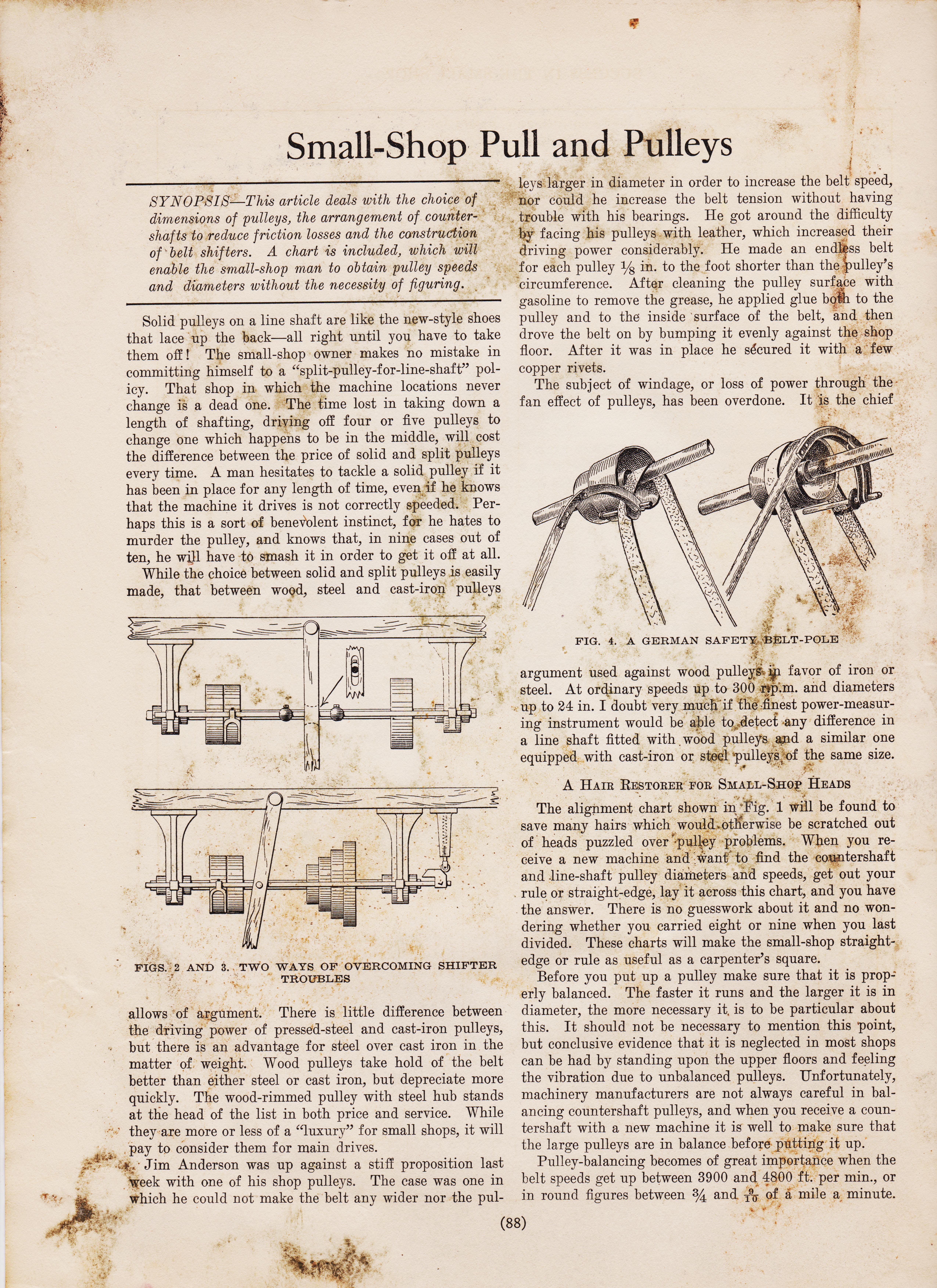
Success-in-the-Small-shop-1914-pg-88-title-page-Lineshafting-pull-and-pulleys.jpeg
alt="https://antiquemachinery.com/images-American-Machinist-Oct-29-1942/pg-1241-Armamet-Tank-Engines-Airplane-made-on-Coverted-Vintage-old-Antique-Equipment-Wristpin-Hole-New-heavy-Fixture-Machine-Shop-Machines.jpeg.jpeg"
&&&&&&&&& 88888888888888888888888888888 208 13 page top
13 down 208 bot http://antiquemachinery.com/images-2020/Machinery-Magazine-March-1896-vol-2-no-7-page-208-bot.jpg
picture from top 13 page title text width="843" height="784" alt="">


