very top text


 Title top text

Sloan & Chase Mfg Co. USA Catalog 1918. Metal Lathe, bench mill, Gear Cutter ect.
Cover of catalog
Sloan-and-Chase-Mfg-Co-Ltd-Same-as-USA-Catalog-1918-color-cover
http://antiquemachinery.com/images-2018/Sloan-and-Chase-Mfg-Co-Ltd-Same-as-USA-Catalog-1918-pg-cover-back-color.jpg
Sloan-and-Chase-Mfg-Co-Ltd-Same-as-USA-Catalog-1918-color-cover
http://antiquemachinery.com/images-2018/Sloan-and-Chase-Mfg-Co-Ltd-Same-as-USA-Catalog-1918-pg-cover-back-color.jpg
I received this catalog
November of 2017 for the
promise that I would find it
good home and be available.
It still cost too much $$$$$$$.
bkgnd
November of 2017 for the
promise that I would find it
good home and be available.
It still cost too much $$$$$$$.
| Sloan & Chase Mfg Co Ltd, Same as USA Catalog 1918 Cover, Index, page 1,2, page 3,4, & page 5,6. |
Click for.....Sloan-and-Chase-Mfg-Co-Ltd-Same-as-USA-Catalog-1918 page 1-2, 3-4. 5-6
Click for.....Sloan-and-Chase-Mfg-Co-Ltd-Same-as-USA-Catalog-1918-page 7-8, 9-10, 11-12, 13-14
Click for.....Sloan-and-Chase-Mfg-Co-Ltd-Same-as-USA-Catalog-1918-page-15-16, 17-18, 19-20, 21-22.
Click here for.....Sloan-and-Chase-Mfg-Co-Ltd-Same-as-USA-Catalog-1918-page-4
Click here for.....Sloan-and-Chase-Mfg-Co-Ltd-Same-as-USA-Catalog-1918-page-5
Cover of catalog
Sloan-and-Chase-Mfg-Co-Ltd-Same-as-USA-Catalog-1918-color-cover
http://antiquemachinery.com/images-2018/Sloan-and-Chase-Mfg-Co-Ltd-Same-as-USA-Catalog-1918-pg-cover-back-color.jpg
bkgnd
Sloan-and-Chase-Mfg-Co-Ltd-Same-as-USA-Catalog-1918-color-cover
http://antiquemachinery.com/images-2018/Sloan-and-Chase-Mfg-Co-Ltd-Same-as-USA-Catalog-1918-pg-cover-back-color.jpg


SPECIAL TOOLS
SLOAN & CHACE MFG. CO. LTD.
Page Index Sloane and Chase
Sloan & Chace Mfg. Co. Plant .(Illustration) . . . . . . . . . . . . . . . . . A
Bench Lathe, with Compound Slide Rest . . . . . . . . . . . . . . . . . . . . 1
Description of 51/2 Bench Lathe . . . . . . . . . . . . . . . . . . . . . . . . . . . . . 2
Milling Attachment (Illustration) . . . . . . . . . . . . . . . . . . . . . . . . . . 3
Description . . . . . . . . . . . . . . . . . . . . . . . . . . . . . . . . . . . . . . . . . . . . . . 4
I~lathe with Screw Cutting Attachment (Illustration) . . . . . . . . '.5
Description . . . . . . . . . . . . . . . . . . . . . . . . ., . . . . . . . . . . . . . . . . . . . . . 6
Screw Cutting Attachment . . . . . . . . . . . . . . . . . . . . . . . . . . . . . . . . 7
Table of Change Gears for English Measure . . . . .. . . . . . . 7
Table of Change Gears f or Metric Measure . . . . . . . . . . . . 7
Revolving Tail Stock....... .. .............................. 8
Boring Rest ............. . ... ... .. ... .......,,... 9
~ready Rest .............. .. . ... .. ................ 10
Double LeVer Slide Rest . . . . . . . . . . . . . . . . . . . . . . . . . . . 11
Drill .I)itclS . . . . . . . . . . . . . . . . . . . . . . . . . . . . . . . . . . . . . . 12
V Centers .......... ...... .. ... .... .. . .. . 12
Face ]'!ates . . . . . . . . . . . . . . . . . . . . . . . . . . . . . . . . . . . . . . . . . 13
~~rinding Attilchme Ill. . . . . . . . . . . . . . . . . . . . . . . . . . . . , 14
Tail Stock ................ .. .... . . .... .... ......... 14
Tool Post Grinder. ..... . ..... .... .. ..... ......... 15
Expanding Chuck . . . . . . . . . . . . . . . . . . . .,. . . . . . . . . . . . . . . . . . . . 16
Spring Collets ............................... .. ........... 16
Step Chucks .......................... .. .. ................ 17
United States Standard Threads. . . . . . . . . . . . . . . . . . . . . 18
No. 2 Bench Milling Machine . . . . . . . . . . . . . . . . . . . . . . . . . . . .19,
20 No. 3 Bench Milling Machine . . . . . . . . . . . . . . . . . . . . . . . . . . . .19,
20 Automatic Pinion Cutters. . . . . . . . . . . . . . . . . . . . . . . . . . . . . . . . .21,
22 No. 1 Automatic Gear Cutter (Illustration) . . . . . . . . . . . . . . . . . . 23
Description . . . . . . . . . . . . . . . . . . . . . . . . . . . . . . . . . . . . . . . . . . 24
No. 3 Automatic Gear Cutter. . . . . . . . . . . . . . . . . . . . . 25,
26 ~~:ngle Spindle Drill Press . . . . . . . . . . . . . . . . . . . . . . . . . . . . . . . . . . 27
Three Spindle Drill Press. . . . . . . . . . . . . . . . . . . . . . . . . . . . . . . 28
Horizontal Tapping Machine . . . . . . . . . . . . . . . . . . . . . . . . . . . . . . . . . 29
Vertical Lever Tapping Machine . . . . . . . . . . . . . . . . . . . . . . . . . . . 30
Vertical Table-Lift Tapping Machine . . . . . . . . . . . . . . . . . . . . . . . 3!
Description of Vertical Table-Lift Tapping Machine . . . . . . . 32
Fractional Inch Equivalents in Decimals and Millimeters . . . 33
SLOAN & CHACE MANUFACTURERS OF PRECISION MACHINERY .
~
SLOAN & CHACE MFG. CO. . LTD.
DESCRIPTION OF MILLING ATTACHMENT
SLOAN & CHACE MFG. CO
DESCRIPTION OF MILLING ATTACHMENT,
shown in the illustration, is mounted upon the top dovetail slide of the compound slide rest, and is fastened by a
latch in the tool post slot. The knee has a full circle graduated base, permitting its adjustment to any angle in a
horizotttal plane, and carries a vertical slide operated by it screw havittg it collar graduated in thousandths of it it
inch. This slide carries a full circle graduated base in which the work hold- ing quill is mounted and is capable of
adjustment to any angle in a vertical plane. The quill is hard ened and ground inside and out, is fitted with a
draw-in spindle, and is made to take either the No. 5 or No. 51/2 lathe chuck.
As shown in the illustration, the slide rest is Inounted upon an off -set shoe that overhangs the !tack of the lathe
bed, giving it a position parallel with the bed instead of crosswise. The milling attachme I Lt is mo fl I tte is ;\,ISO
made, if so ordered, with a running sililt
pg-
page 1 and 2
SLOAN & CHACE MFG. CO., LTD'
CAPACITY:
--7" swing, 18" between centers (bed 35 inches long) , 5/s " through draw-in spindle, ~" with draw- in spindle
removed.
H EA D of the No. 51/2 Lathe carries a hardened and ground spindle having straight cast iron bearings fitted in
taper sleeves
having threads cut upon each end upon with ajusting nuts are mounted; by loosening one nut and tightening
the other, the wear of the spindle is taken up,
A hardened and ground collar, screwed Into the small end of the pulley and taking its bearing upon the inside of
the front bushing, provides the adjustment for taking up the end play. The end thrust is taken upon the front
shoulder of the spindle. The front end of the spindle has an outside thread and straight bearing upon which
large face plates and chucks may be carried.
The spindle collets are very long , are of the self -centering spring type, and have a twelve degree angle. The
cone pulley has a row of 120 holes in the outer flange. accuratel~' spaeccl. in which an index pin opera!~s,
giVing sub- divisions of 60, 40, 30, 24, :'-CI. 15. 12. 10, S, 6. 5, 4, 3 and 2. The cone steps are 1~~~ " wide.
TA IL STD C K
is of the ~`off -set" type-the casting curving outwardly toward the back of the lathe ~ leaving the center
over-hanging, thus allowing more room for manipulating the slide rest screw. It is bored in special fixtures which
insure perfect alignment and interchangeability.
BED-WAYS
are of the standard Sloan & Chace .double V type which, while more expensive to build than the Hat beds of
other lathes, has proven much superior in actual service. The double V construction gives the best grip and a
more uni- form wear. The bed-ways and bases of all fixtures are scraped to master gauges, and we guarantee
correct centers and alignment.
COMPOUND SLIDE REST
is supported on a shoe having beveled sides at right angles to the bed-ways. The shoe is held to the bed-ways
by means of a coiled spring, and is firmly fastened by a binder bolt alld spider nut. The tool post slide has a
circular base graduated to a full circle of 360 degrees, permitting the slide to be set at any angle. The slide
screws are 20 threads per inch, have a travel of 41[2 inches, and have collars graduated to read in thousandths
of an inch, and have adjustable cone bearings which permit of instantly taking up all lost motion.
All moving parts are hand scraped to perfect fits, and the design and construction of the slide rest gives a
maximum of strength, rigidity and accuracy, By employing an off -set shoe the slide rest may be mountcd on
either side of the lathe bed, front or back, and in ~L,ner right or left hand positions, thus performing all con<
~ivable operations.
COUNTERSHAFTS
are made in two styles-Wall and Wall- Rod. The wall countershaft is built with either two or three speeds (the
third speed being used to revolve the lathe back- ward for such work as thread cutting ) . .eee' The wall rod
countershaf t is built with either one or two speeds. A grinding countershaft, used in connection with the
Grind-ing Attachment, can be mounted with either the wall or wall- rod countershafts. AH countershafts are
equipped with ring oiling bearings which require attention only at long intervals.
GROSS WEIGHT of Lathe Boxed, 230 tbs.
DIMENSIONS of packing case, 42" x 16" x 16".
pg 2
SLOAN & CHACE MFG. CO. . LTD.
DESCRPTION OF SCREW CUTTING ATTACHMENT
page 6
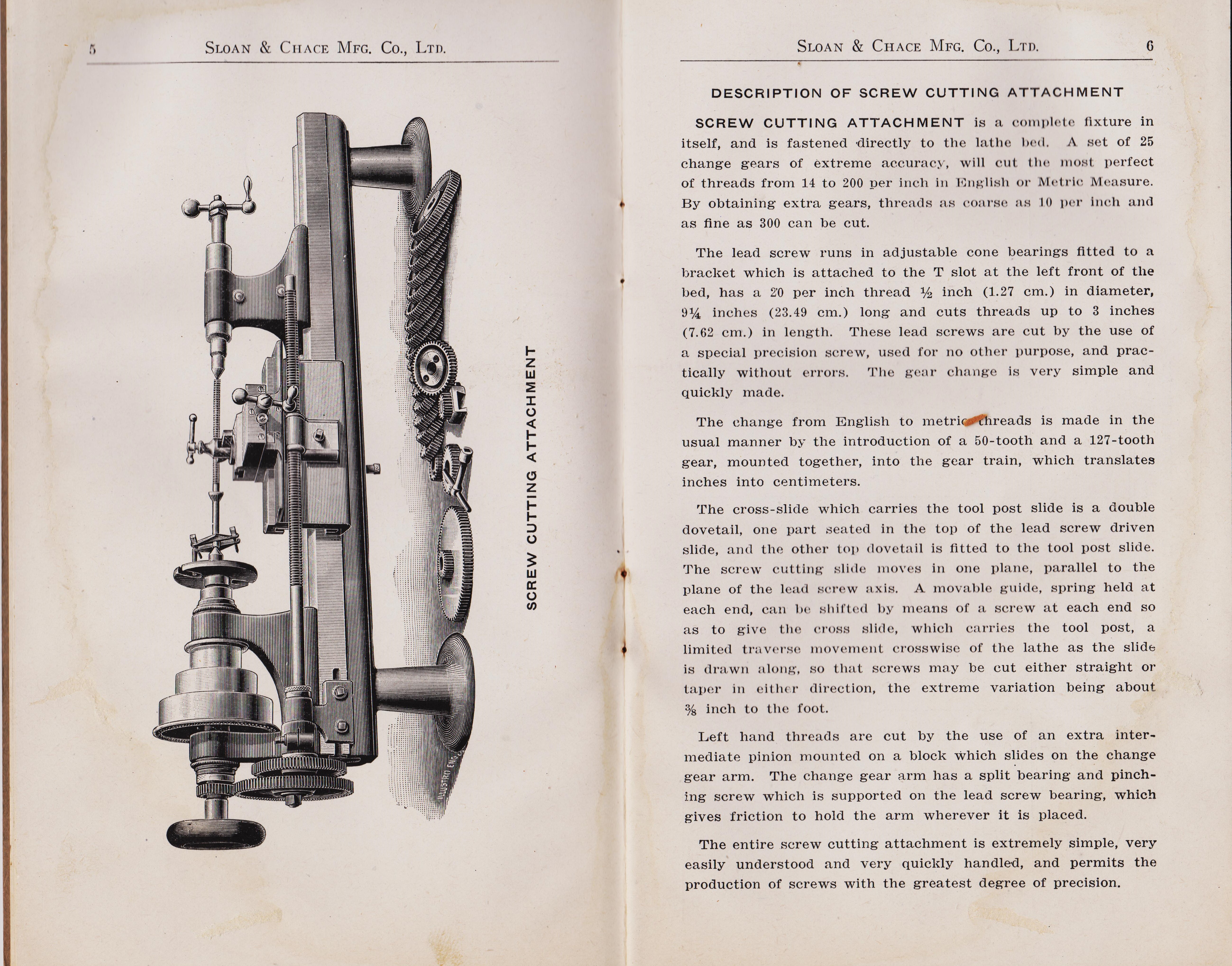
SCREW CUTTING ATTACHMENT
is a complete fixture in itself, and is fastened 'directly to the lathe bed.
A set of 25 change gears of extreme accurac3-, will cut the most perfect of threads from 14 to 200 per inch
English or Metric Measure. By obtaining extra gears, threads as coarse as 10 per inch and
as fine as 300 can be cut.
The lead screw runs in adjustable cone bearings fitted to a
bracket which is attached to the T slot at the left front of the bed, has a ~ per inch thread per inch (1.27 cm.) in diameter,
9~ inches (23. 49 cm. ) long and cuts threads up to 3 inches (7.62 cm. ) in length, These lead screws are cut by the use
of a special precision screw~ used for no other purpose, and practically without errors.
The gear change is very simple and quickly made.
The change from English to metric threads is made in the usual manner by the introduction of a 50-tooth
and a 127-tooth gear, mounted together, into the gear train, which translates inches into centimeters.
The cross-slide which carries the tool post slide is a double dovetail, one part seated in the top
of the lead screw driven slide, and the other top dovetail is fitted to the tool post slide.
The screw cutting slide moves in one plane, parallel to the plane of the lead screw axis.
A movable guide, spring held at each end, can be shifted by means of a screw at each end so as to give the cross slide,
which carries the tool post, a limited traverse movement crosswise of the lathe as the slide is drawn along,
so that screws may be cut either straight or taper in either direction, the extreme variation being about a/s inch to the foot.
Left hand threads are cut by the use of an extra intermediate pinion mounted on a block which
slides on the change gear arm. The change gear arm has a split bearing and pinching screw
which is supported on the lead screw bearing, which gives friction to hold the arm wherever it is placed.
The entire screw cutting attachment is extremely simple, very easily understood and very quickly handled,
and permits the production of screws with the greatest degree of precision.
DESCRPTION OF SCREW CUTTING ATTACHMENT
page 6
SCREW CUTTING ATTACHMENT
is a complete fixture in itself, and is fastened 'directly to the lathe bed.
A set of 25 change gears of extreme accurac3-, will cut the most perfect of threads from 14 to 200 per inch
English or Metric Measure. By obtaining extra gears, threads as coarse as 10 per inch and
as fine as 300 can be cut.
The lead screw runs in adjustable cone bearings fitted to a
bracket which is attached to the T slot at the left front of the bed, has a ~ per inch thread per inch (1.27 cm.) in diameter,
9~ inches (23. 49 cm. ) long and cuts threads up to 3 inches (7.62 cm. ) in length, These lead screws are cut by the use
of a special precision screw~ used for no other purpose, and practically without errors.
The gear change is very simple and quickly made.
The change from English to metric threads is made in the usual manner by the introduction of a 50-tooth
and a 127-tooth gear, mounted together, into the gear train, which translates inches into centimeters.
The cross-slide which carries the tool post slide is a double dovetail, one part seated in the top
of the lead screw driven slide, and the other top dovetail is fitted to the tool post slide.
The screw cutting slide moves in one plane, parallel to the plane of the lead screw axis.
A movable guide, spring held at each end, can be shifted by means of a screw at each end so as to give the cross slide,
which carries the tool post, a limited traverse movement crosswise of the lathe as the slide is drawn along,
so that screws may be cut either straight or taper in either direction, the extreme variation being about a/s inch to the foot.
Left hand threads are cut by the use of an extra intermediate pinion mounted on a block which
slides on the change gear arm. The change gear arm has a split bearing and pinching screw
which is supported on the lead screw bearing, which gives friction to hold the arm wherever it is placed.
The entire screw cutting attachment is extremely simple, very easily understood and very quickly handled,
and permits the production of screws with the greatest degree of precision.